![]()
|
|
|
|
|
|
|
|
|
|
|
|
|
|
|
|
|
Background
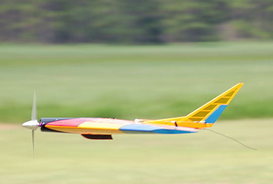
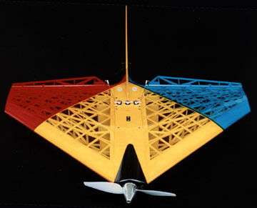
Mike described a fairly standard delta wing design having about 400-450 inches of wing that would weigh no more than 32 oz, which happens to be the thrust rating of the motor. He wanted the plane to be aerobatic and fly in the 50-60 mph range. Thwing! is a collaborative design between myself and Mike using his basic parameters as a starting point. We laid out the design in about an hour using markers on my glass work bench. Once we had the basic idea down, we pulled out a sheet of paper and started laying out the drawing more or less to scale. That took about another hour. From there I drew a set of plans I could build from. Drawing the "plans" basically entailed drawing two airfoils, a top view and a bunch of spars. I made up the rest as I was building. I was trying to maintain a theme of a 50's sci-fi submarine as far as styling goes — sort of a manta look. We considered upswept wing tips but decided that they could be added on later if we still want them. Mike is an excellent pilot but he is not a builder. That left me to work out the construction details as well as build the thing. Mike was really great at helping to add tedious features though. For example, when I mentioned that we could try a cap-strips-over-spars wing structure, Mike became fixated with each wing panel having 6 spars (12 total).
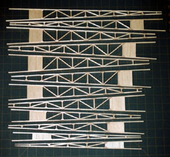
Not wanting to be outdone in the tedium department, I mentioned to Mike that it might be neat to build lattice wing skins instead of simply using cap strips over the spars. At the time I wasn't sure how well it would work but knew that if it didn't then we could revert to the cap strips. We had several discussions about how the lattice skin would affect the aerodynamics but we knew that we'd have to fly the model before we'd really know anything. In the mean time Mike called it the "golf ball airfoil." As I visualized the airfoil I considered that if I were an air molecule, Thwing! would be fun to flow over. The theory behind this wing design is that a root and tip airfoil define the entire wing panel. Each airfoil is divided into an equal number of segments (spar locations). Each spar is a straight line from root to tip. They do not need to be located at the same percentage chord for each rib, but that's the way I chose to do it. When a skin (or cap strips) is laid over the spars it creates a very accurate airfoil for the entire panel.
|
|
|
ConstructionAs it turned out the model was not as difficult to build as it may look but it was monotonous thanks to the contest between Mike and I to see who could come up with the most tedious feature and then me deciding to incorporate each of those ideas. I think Thwing! is the most structurally attractive flying model aircraft I've ever built so it was worth it. I'd conservatively estimate that I have 200+ hours in building the model. It took about 5 weeks to complete.
The leading and trailing edges would be tall enough that they could suspend the wing off the board with either side up. The edges would remain over size until all the skins were glued on at which point it would be nearly impossible to warp the wing. To accomplish all of this I had to ensure that the leading and trailing edges were cut absolutely parallel and to the exact same height. The sub-edges needed to be glued on extremely accurately on the centerlines of the outer edges. If all these things are accomplished then the wing will be as straight as the board it is built on. The root and tip ribs were notched to slide onto the sub-edges. At the time I first had this idea I thought that it would work ok but that I'd probably come up with a better way to build the wing. It actually turned out to be the simplest method I could think of and it resulted in an extremely straight wing. In other words I would do it again.
I had to cut 3 sets of lattice before I had one that would work. The first set cocked while I was routing it which resulted in the lattice spacing not being the same across the sheet. I didn't notice that had happened until I started assembling it. The next set was made from contest balsa and I was afraid it wouldn't be strong enough. I feel the contest balsa could have been used now that the wing is completed. Having never built a wing like this before I wasn't sure how much strength it would have nor how much it needed to have. I didn't want to take chances so I ended up using medium balsa. All the lattice used was cut from a single sheet of 3/32" x 4" x 48" sheet. The router did not cut the joints cleanly. Before cutting the sheet into strips, I sanded as much fuzz off as possible. That only took care of fuzz near the face of the sheet. After the sheet was stripped I used a needle file to individually clean every joint. Fitting the lattice skin to the wing turned out to be more difficult than I thought it would be. That was because of the oversize leading edge which did not allow me to drop on the over-size skin to mark it for trimming. Because of the curve of the airfoil, the skin has to be larger than what is shown in top view.
Overall I would say the weight of the plane is similar to what it would be using more standard construction techniques. It looks a lot better. On the other hand, the wing is torsionally the stiffest that I have ever built and I can only attribute that to the lattice. From a design and style standpoint, the item that gave us the most difficulty was the vertical stabilizer. We knew we wanted a rudder because the Aggressor tends to drift in climbs and there is no way to correct it. What gave us trouble was finding a fin/rudder shape that blended into the overall theme while having enough surface area. We spent hours drawing fin and rudder shapes and just couldn't come up with a shape we liked. In all cases the fin was shaped such that the leading edge was vertical or rearward swept. The trailing edge was always forward swept. Whenever we had a shape we liked, it didn't have enough area. We contemplated adding a sub-fin but were concerned about it being damaged in landings. All the while we were designing a fin that would be glued on so that its trailing edge was aligned with the elevon hinge line. The bottom of the rudder would be cut at an angle to allow elevon movement. I've never seen a plane with a rudder like that that I've liked — it's just a really ugly rudder shape. In frustration I finally drew some very sharply raked lines for both the leading and trailing edge. Both of us looked at it and realized that we had something we were going to like. I went to work on other things and left Mike to continue tweaking the lines and working out the area. Of course this fin design gave us a whole new problem — how to hold it on. Gluing the fin to the upper deck sheeting alone would be really precarious. There would be too much unsupported area hanging off the rear of the wing. We had discussed adding a "stinger" a few weeks prior as strictly an ornamental thing. Now it would have a purpose. Of course this added another new problem. The elevons were already built such that they would meet in the center of the wing with a minimal gap between them. I ended up chopping off a good amount of area to make room for the stinger. They still have plenty of area and are very effective even though the loss of area was directly in the prop blast.
In the mean time the leading and trailing edges could not be cut down and shaped until after the lattice was glued on so we had to visualize almost to the very end of construction. By that time the model was virtually finished. One last very tedious item remained. I had to edge the lattice at the root, trailing edge and wing tip. I just didn't trust the small amount of contact area not to break loose in a high G maneuver. The edging entailed cutting and fitting a whole bunch of tiny pieces and even tinier triangles. Each one was hand fit. At this point all that was left to do was make the cowl, finish the hatches, finalize the motor mount, sand everything and then finish it.
|
|
|
FinishDeciding on a color scheme was the one other area besides the designing the fins where we got stuck. Mike really likes the Oracover transparent orange on Bride of Gonzo and said he wanted Thwing! to be orange. I asked, 'Orange and what?' Mike replied, "Orange." Ok, so Mike wants an all orange flying wing. I was pretty sure I could convince him otherwise before actually doing it. When the time came to cover we pulled out all of the transparent colors I have and started putting swatches together on and off the plane. We probably spent 3 hours just trying to decide what colors to use.
The covering is comprised of transparent Oracover and Oracover Lite. The whole wing could be covered in Oracover Lite, but the regular Oracover transparent orange is warmer and a nicer color overall. I was in a big hurry to finish the cowl. It is a small piece so I managed to glass, prime and paint it in less than 24 hours. Klass Kote primer and paint were used. I sprayed on one medium-heavy coat of black using my Aztec airbrush. It didn't need more because the one coat gave excellent coverage and a super gloss. Overall it was a very interesting project and something out of the ordinary. I can see doing more models having the same type of construction because it is strong, light, rigid and very pleasing to look at.
|
|
|
Flying Thwing!
The elevons were very sensitive to the controls which we expected because we gave it more throw than we thought we would need to ensure there would be enough to control it. The model flew well once it was trimmed for straight and level flight. It is very solid and is faster than we expected but it is by no means a speed demon. Slow speed tests of the model revealed a very steep glide slope of about 40 degrees. This is at speeds slower than we would attempt to land it. The wings begin to rock slightly, but there is no tendency to tip stall. It just sinks really fast. Controls worked at the slowest speeds we achieved with the model. I thought the "golf ball" wing skin would exhibit noticeable drag, but it doesn't seem to hold the model back. A few months after the first flights we tried a higher pitch prop. The model scooted along much faster but the launch was a little more sluggish due to the poor acceleration characteristics of high pitch propellers. Mike didn't like the way Thwing! climbed out after launch. It didn't have the acceleration of the original propeller. However, this was using the motor that had pulled from the mount on the second flight. The motor didn't run too smoothly and we suspect the shaft was bent. We didn't bother trying to find out what was wrong with it. Mike simply replaced it with a new motor. My belief is this model is capable of much higher speeds than have been reached so far. It appears as though the limiting factor has been thrust and not drag at the highest speeds the aircraft has reached. It has also shown no tendency to flutter.
What actually happens is that we never know what the rudder is going to do. Sometimes it causes the nose to tuck. Sometimes it rolls the model in the expected direction and sometimes it rolls the model in the opposite direction. What it doesn't do very well is correct the heading so it's been pretty much useless except for entertainment value. Other than the rudder's emotional problems it looks like we hit a home run with this one — especially considering it's a prototype. By the way, the exclamation is part of the name, Thwing!. Whenever you mention the airplane in conversation you are obligated to say it with exuberance. Also, you have to hold the "ing" part for an extra second. Sort of like "Thwiiinnnggg!!!!" Those aren't my rules. It's just the way English works. We appreciate your conformity. Thank you.
|
|
|
|
|
|
|
|
|
Copyright © 2004-2006 Paul K. Johnson
|
|


 Mike has been having a blast flying my
 I
was all for having 4 spars and possibly 5 if when I drew the plan it seemed like
more support was needed. But Mike insisted that 6 spars were necessary so
Thwing! has six pairs of truss-work spars. That's what I get for letting
other people hang out in my shop (which I keep reminding Mike is a privilege,
not a given right).
I
was all for having 4 spars and possibly 5 if when I drew the plan it seemed like
more support was needed. But Mike insisted that 6 spars were necessary so
Thwing! has six pairs of truss-work spars. That's what I get for letting
other people hang out in my shop (which I keep reminding Mike is a privilege,
not a given right).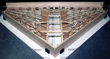 Before
I could do much of anything I had to figure out how I was actually going to build a
wing that has only 2 ribs. I decided to support the root and tip ribs on a
sub-leading edge and sub-trailing edge.
Before
I could do much of anything I had to figure out how I was actually going to build a
wing that has only 2 ribs. I decided to support the root and tip ribs on a
sub-leading edge and sub-trailing edge.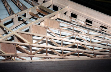 I thought that building the spars would be the bulk of the work and the rest
of the construction
would pretty much fall together afterward. Unfortunately the lattice
was more of a project than I expected.
I thought that building the spars would be the bulk of the work and the rest
of the construction
would pretty much fall together afterward. Unfortunately the lattice
was more of a project than I expected.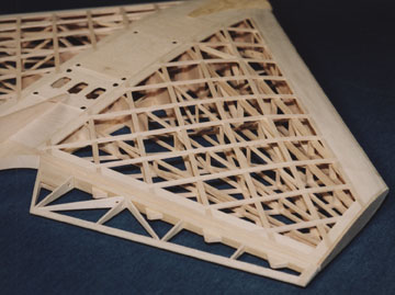 I made a cutting jig to trim the rear corner at the
root of the wing. The idea was to ensure all the skins had an identical
base point. Once that corner was established, the other edges of the skin
were trimmed to fit.
I made a cutting jig to trim the rear corner at the
root of the wing. The idea was to ensure all the skins had an identical
base point. Once that corner was established, the other edges of the skin
were trimmed to fit.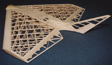 As
the model began coming together we became more anxious to see it completed in
the bare bones. It was obviously going to be very attractive.
As
the model began coming together we became more anxious to see it completed in
the bare bones. It was obviously going to be very attractive.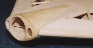 This
was a case where we just got lucky. Neither of us really knew what would
look best on the plane, but eventually we slid some pieces on the wing more or
less like it is now and we both immediately liked it.
This
was a case where we just got lucky. Neither of us really knew what would
look best on the plane, but eventually we slid some pieces on the wing more or
less like it is now and we both immediately liked it.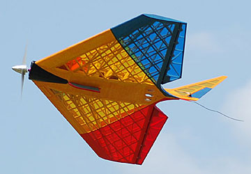 The maiden flight of the model showed that we had given the elevons too much
reflex causing the model to immediately begin a steep climb.
The maiden flight of the model showed that we had given the elevons too much
reflex causing the model to immediately begin a steep climb.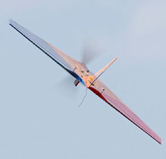 Although we installed a
rudder to make heading corrections, we didn't know what to expect from it.
I expected the rudder would tend to hold the nose up because the hinge line is
sloped rearward.
Although we installed a
rudder to make heading corrections, we didn't know what to expect from it.
I expected the rudder would tend to hold the nose up because the hinge line is
sloped rearward.