![]()
|
|
|
|
|
|
|
|
|
|
|
|
|
|
|
|
|
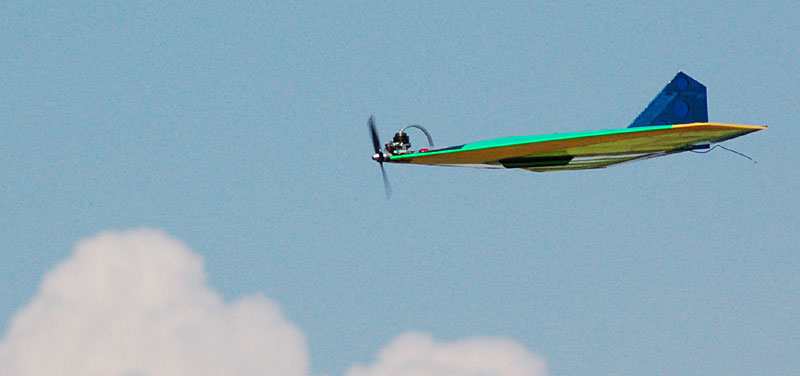
JGRC Aggressor Flight VideoThis is a compilation of two separate flights. The only flying I did in this video is the actual launch. The rest of the video is a prior flight with Mike Phillips at the controls.
|
|
|
About the JGRC AggressorThe Aggressor is the first kit marketed by JGRC, a local company that specializes in electric aircraft. I spoke with the owner, Jeffrey, at the 2004 Vintage Radio Control Society Fly-In held in Spring Hill, Florida. At that time I was about a week from completing my Rustik project and was looking for something quick and mindless to assemble. Sort of an anti-Rustik. Because I have a glass cabinet full of glow engines and know nothing about e-power or have any equipment for it, I wanted something that could be easily converted to glow. Jeffrey immediately pulled out his Aggressor kit and told me it can be built in a day. The rakish lines of the delta flying wing really appealed to me as well as it being a very simple model having a low parts count with some unique construction methods. Additionally, I have only built one flying wing and it was a disaster of my own design, so this would be a step away from the usual for me. As soon as I got home I poured out the contents of the kit and looked it over to see what I would have to do to modify it to glow. Once I had a good idea of how the kit went together, I put it all back in the box and proceeded to finish Rustik.
|
|
|
Construction
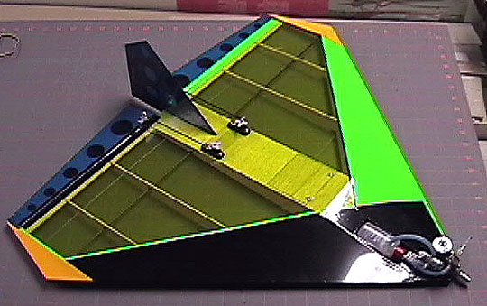
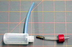
There is no plan, but the instructions are photo illustrated. The photos in the manual appeared to be multi-generation copies and in some cases it was difficult to figure out what was going on. In general, the instructions could be significantly improved. In addition to the photos, some things are not adequately addressed. For example, the kit is designed for a Speed 280 to Speed 400 power system but other than telling you where it goes, the instructions only indicate that the prototype had the engine strapped on with zip ties. Had I wanted to use e-power for mine, I would have had no idea what to do. Although the basic airframe can be built in one day, it would take a considerable effort to have the plane ready-to-fly in one day. The basic airframe notches together quickly, but then there is a lot of fiddling around with the usual things. Before I could start building there were several things I needed to resolve. As I already mentioned, I converted mine to .061 (1/2A) power. I cut out two identical 1/16" plywood plates make up the engine mount. One of the plates took the place of the balsa doubler under the wing and the other went on the top of the wing. I set up the engine to have about 3° right thrust. A good part of the time I spent before beginning assembly was fiddling around with bottles to use as a fuel tank. Initially I tried a Kodak Advantix film canister, but I did not trust it not to leak. Eventually I made a tank from a small bottle I purchased to use as a glue bottle. The cap is drilled slightly smaller than a fuel tube. The feed line is pulled through this hole. On the top side of the bottle is the pressure line. It is also simply pushed into the hole and extends into the tank about 1/16". This arrangement has worked fine so far.
In addition to making the tank, I had to figure out how to mount it. Originally I was going to place it inside the structure and just cut away the sheeting as necessary to clear the front of the tank. However, if there were any problems with the tank that would require its removal, then I would have had to cut into the model to get at it.
I did not have any fuel-proof black paint, so I used Humbrol enamel around the engine and fuel tank areas and then over-coated them with clear polyurethane. I really like the way the parts are designed to lock together. Because a laser cuts at an angle and there is really no way to sand the dovetails and maintain the fit, one side of multi-part components has a slight, but not objectionable, gap. The ease and accuracy of assembly makes most of the assembly idiot-proof. One thing that I really did not like about the design is that the center ribs are the correct height without the sheeting that sits on top of them. What that means is that the covering will be completely suspended until it can be ironed down to the spar at some point out from the center section. I think the model would be better if there were rib doublers for the inside of the center ribs. The sheeting would sit on the doublers and inside the main ribs. The doublers would be 1/16” below the main rib so that the sheeting is flush with the ribs. That would make the outside of those ribs look neater as well as resolve the higher center section issue. I added balsa filler pieces to fair the spar from the center rib to the second rib so that I would have something a little better to adhere the covering to. It also provides a landing to terminate the covering so that I could do the scheme that I chose. If the underside of the fuselage is built according the instructions, there will be a large opening at the front of the airplane. I am not sure what that is about because it is not mentioned one way or the other. I can only assume that it is a typo or possibly for cooling the motor batteries. However, because the opening is like a shark's mouth at the front of the airplane, it seems like it would be susceptible to damage on landing. A set of plans — even 1/2 size would have been nice to clear some of these things up. I simply sheeted all the way to the nose and did not worry about it. The airframe has carbon fiber tube leading edges that I epoxied on to the balsa leading edge pieces. The balsa pieces would have been strong enough on their own, so I have no idea what the purpose of the carbon tubes is. Possibly to strengthen the leading edge on landing as the plane has no gear. Radio InstallationThe instructions call for a pair of Hitec HS-55 servos for the elevons. I do not have any of this model servo, but I do have HS-50's that are significantly lower in torque and slightly smaller (according to the specs on the Hitec website). If you follow the instructions and use the indicated servos, then there will be a problem with the servo leads coming through the bottom sheeting and hanging in the breeze.
Instead of using the hardwood rails which would have made it very difficult to insert and remove the servos due to the grommet around the servo leads, I used two pieces of 1/16" plywood that are flush with the top sheeting instead. The rails are backed with 1/4" square pieces of the same plywood to give the screws something more to bite into. Again, it was hard to tell what was going on in some of the photos, but it looks like the instructions have you leaving the servo area unsheeted across the wing. if that is the case, then the included rails could be used by cutting a notch in them and sliding the servos over to the notched area to remove them. Personally, I do not like openings in my airplanes because they screw up the aerodynamics. Additionally, exhaust from the engine likes to go in those places and never come out again. The latter, of course, would not be an issue with E-power. I filled the area between the servos with some scrap sheet. This is the first R/C airplane that I have glued my radio in. There simply was not room for foam around the receiver I used. There are several smaller receivers available, however. I used silicone to attach the receiver, battery and throttle servo. The other thing I needed to figure out was the receiver antenna. I do not have any base-loaded antennas and really did not want to buy one, so I tossed the idea around for a bit and finally installed a piece of .020 music wire permanently in the airframe. The antenna was cut from the receiver leaving just a piece about 5" long. Together with the music wire, the antenna is the original length. The antenna has a small bend to secure it in one wing tip and then runs parallel to the trailing edge. Before reaching the opposite wing tip, it loops forward and enters the center of the wing where it is attached to the receiver. This arrangement range checked fine so I left it installed. The first day at the field, the radio went berserk when the engine was running. We discovered that unplugging the antenna made the problem go away. We do not really know what the problem is, but a couple things were happening. First, the #2 wood screws holding the engine to the mount vibrated loose causing the fuel to become nothing but foam. That is a lot of vibration. Second, the antenna wire contacts the rear carbon fiber spar which may be causing some type of problem as well. In any case, I put the original antenna back on and just let it hang out the rear of the aircraft. It is not pretty, but it works.
|
|
|
FlyingAnother error I found in the manual states that the Center of Gravity should be from 9" to 9-1/2" from the front of the plane. Further, the manual says that 9-1/2" is where rib 3 meets the leading edge. In actual fact, rib 3 meets the leading edge at 10" behind the front of the airplane. This left me confused as to where the actual CG should be. For initial flights, the CG was at 9" which worked fine. One item that was omitted from the manual was the neutral position for the elevons. The suggested throws are 3/8" total (3/16" each direction), but no place was the starting point mentioned. The airfoil is not reflexed and being a flying wing I assume the controls must be reflexed slightly. Even if they are supposed to be set at neutral, some mention of this would provide a little peace of mind for the test flight. Because of the radio problem on the first day out, I had to take the Aggressor home and work on it. The antenna was changed as previously indicated. I also drilled out the holes for the engine mounting screws and replaced the wood screws with bolts and lock nuts. That resolved the vibrating loose problem as well as significantly lowering the overall vibration throughout the airframe. The plane can only be hand-launched which is not difficult at all. The engine has plenty of power and the plane is flying immediately upon launch. I gave it a gentle toss with the nose pointed slightly up while Mike did the flying. As it turns out, I was right about the neutral setting for the control throws. On the first flight we almost ran out of up elevator trim just trying to get the model to fly straight and level. Approximately 1/16" of up elevator was necessary. I simply turned the servo arms one spline and then made a small adjustment using the sub-trims on my transmitter as the pushrods have a Z-Bend on each end, so they are not adjustable. That setting allowed us to put the trims back to neutral and try again. The second flight took very little trim to get the plane straight and level. The Norvel has a very sensitive needle, so we adjusted it one click per flight. By the last flight of the first day, the engine was really singing and throttled well. Until we got the engine pretty close to it is final setting, we could not go below half-throttle or the engine would die. The stock head was leaking around the glow button, so I replaced it with a Cox glow head. Flying the plane is a blast, but it is the type of plane that if you take your eyes off it, it will be in the gone before you know it. It is not as fast as I thought it would be, but some experimenting with different props and fuels as well as some more break-in time and getting the needle set will probably give a few more MPH. Mike dialed in a bunch of expo to make the controls less sensitive around neutral. The first flight was kind of hairy with the trim problem and the touchy controls. Mike handled it fine as he always does. One thing I would probably change if I were to build another one is to add a rudder servo. My plane came in nose-heavy anyway, so the added weight could be put to some good. I do not think the rudder would be very effective for aerobatic maneuvers, but that is not why I want it. I would just like to be able to make yaw corrections — particularly on vertical lines. My overall impression of the model is mixed. I feel for the $45.00 advertised price that the instructions should be improved, a couple more pieces of hardware could be included, a more detailed motor mounting instruction could be provided and the photos in the manual should be clearer. However, if you are an experienced builder, the build is a no-brainer. On a cost per grin basis, the Aggressor is cheap fun. Mike wants me to build him a larger version for E-power, so that may be in the gallery soon.
|
|
|
|
|
|
|
|
|
|
|
|
Copyright © 2004 Paul K. Johnson
|
|


 jgrc_aggressor_01.wmv
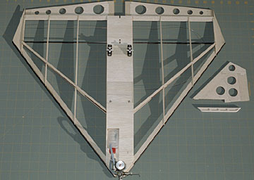 The box contains an instruction manual, several sheets of laser-cut balsa,
three 1/8" carbon fiber tubes, a pair of hardwood servo rails and a pair of
micro control horns.
The box contains an instruction manual, several sheets of laser-cut balsa,
three 1/8" carbon fiber tubes, a pair of hardwood servo rails and a pair of
micro control horns.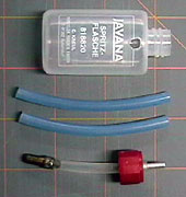
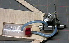
 Instead, I simply built an open compartment by cutting some sheets to close
off the structure while leaving the tank entirely accessible. The tank is
retained with strategically placed drops of silicone sealant.
Instead, I simply built an open compartment by cutting some sheets to close
off the structure while leaving the tank entirely accessible. The tank is
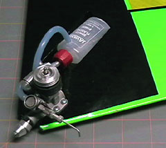
retained with strategically placed drops of silicone sealant.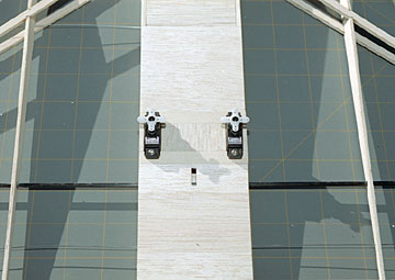 The photo on the box cover shows the servos mounted farther forward which is
how I mounted the Futaba S3106 micro servos that I chose
for the elevons.
The photo on the box cover shows the servos mounted farther forward which is
how I mounted the Futaba S3106 micro servos that I chose
for the elevons.