Airfield Models - How To

Make Variable Angle Magnetic Fixtures

December 19, 2021


Home
About
What's New
History
Models Gallery
Model Building Safety
Articles
Mail & FAQ
Site Map
Site Feedback
Contact
Add to Favorites
Comments
Search Airfield Models

Back to Magnetic Building System


Airfield Models (http://www.airfieldmodels.com/)How to Make Variable Angle Magnetic Fixtures

Soon after I made my first magnetic fixtures I began pondering how to make variable angle fixtures for times when I need to 
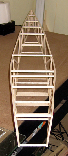
jig something that isn't 90° to the building board.  For example, most flying boat hulls have angled sides.

I always had in my mind that the worst case would be making fixtures specific to the project that are cut at the correct angle for whatever is being jigged.  That approach isn't very efficient and I'd probably never use the fixtures for anything else but I'd be able to complete the project.

From the time I began building with magnets to this day I haven't had a project requiring a fixture at an angle other than 90°.  What it came down to was I had challenged myself to come up with a solution even though I didn't have a use for them.

Over the past several years I've tried a couple approaches starting with what seemed to be the simplest.  All my initial attempts were variations of the same idea cut a radiused slot that allows the fixture to rotate on the bolts that secure the magnet.  I've cut slots like this in the past for other purposes and they never came out very good.  I've tried rotating the piece on a pin and using a scroll saw but the blade wandered all over.  I've done the same thing using my router table with equally poor results.  I've also just cut free-hand on my scroll saw and it was better but still not good.

In regard to the fixtures, even when the slot was useable the idea simply didn't work for several reasons:

  • The fixture didn't rotate smoothly due to the poorly cut slot.  This made it difficult to set the required angle.

  • The range was very limited.  I don't remember the exact number but I think at most I could get somewhere in the 20° to 30° range.  That probably would have been fine for most practical purposes but I wanted the fixtures to have a wider range.

  • The fixture face didn't come all the way to the board because the edge of the fixture needed to be radiused to allow the fixture to rotate.

  • For reasons I still haven't determined, the fixture had no holding power at all.  Even the slightest bit of force lifted the magnets from the board.  I tried arranging the magnets differently, adding more magnets and more steel poles but the result was always the same.  I'm guessing the force against the fixture just had more leverage than the closely spaced magnets could withstand.

The radiused slot approach was a failure and I gave up on it.  Up to then I wasn't real concerned about the rotational range or size of the fixture.  I just wanted a starting point that I could build from.  
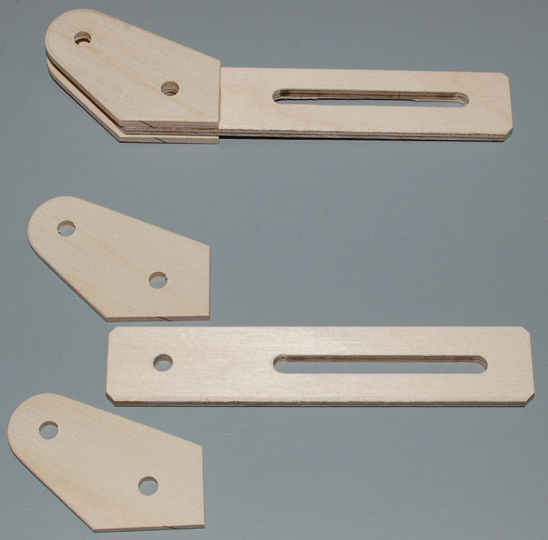
What I realized is that the fixture wasn't going to be a simple one-piece affair.

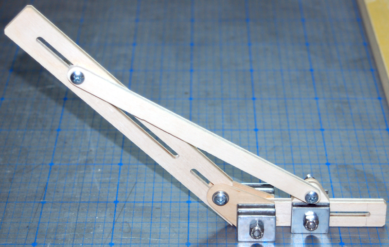
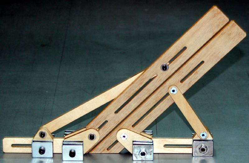
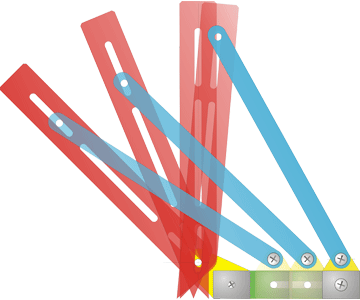
I was, however, confident that a triangle with three adjustable angles would work but would also be much more complicated and require working out the geometry.  So that's what I did.  A specification was no longer optional but it was pretty simple:

  • The fixture must have unlimited adjustment range from 45° to 135°.

  • The wider the base, the more rigid and stable the fixture will be.  I arbitrarily decided that the maximum width of the fixture base must not exceed 6" at any angle setting because it didn't seem unreasonable to have a building board 12" wider than whatever is being built.

  • The fixture face must touch the board at any angle to fully support the item being jigged.

  • The angle must be securely locked in place once set.

  • The fixture must have reasonable holding power, e.g. can not pop loose from the steel board too easily.

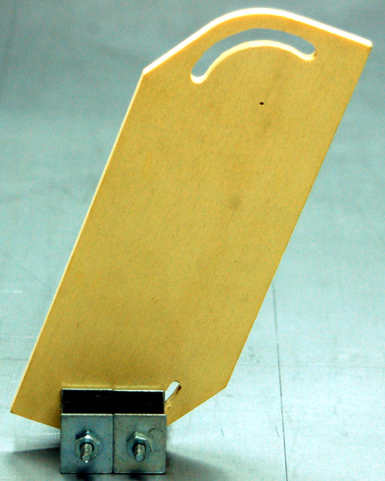
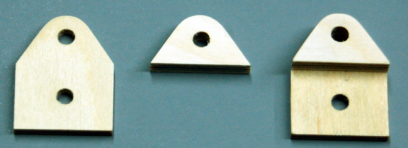
My final design is the simplest that I could make work well.

This project doesn't require parts to be fabricated to extremely accurate tolerances.  However, the more accurate everything is the better it will work.  The movement will be smoother and there will be less play which will make it much easier to set the required angle accurately.

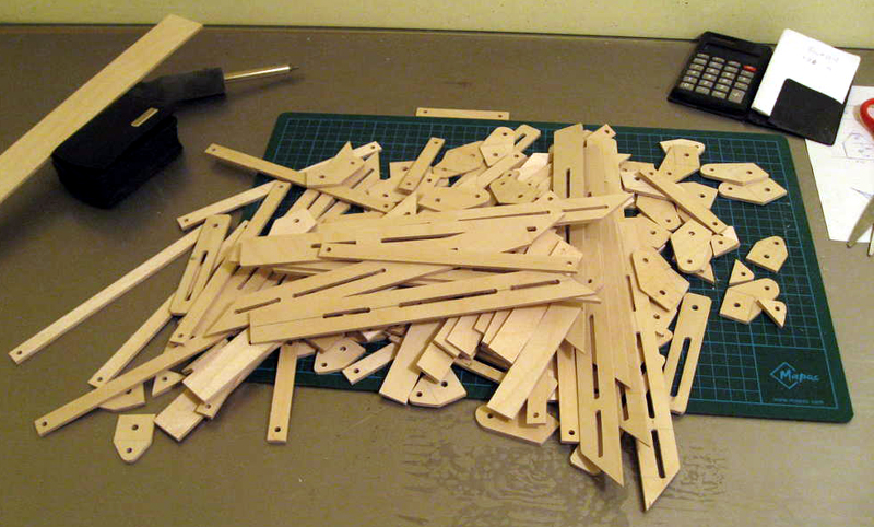
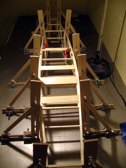
I made one prototype.  It worked very well so I went on to make four more fixtures with slight revisions.  As soon as they were done I realized that the hardware could be changed to make the fixture much easier to work with and I made another four fixtures.


An idea for a variable angle fixture. This was my first idea for a variable angle fixture.  At the time I knew the drawing wasn't very close to what would be necessary and I never even attempted to make this one.

Even though I knew this idea wouldn't work as is, I didn't realize how bad the fundamental idea was until I made a couple prototypes that were complete failures.

This design was a failure. This design had numerous problems:
  • It was very difficult to cut the slot accurately.  The slot was sticky and then it was sloppy after continual trimming to remove the stickiness.  I'd probably need a milling machine to make the slot accurately.

  • The angle range was very limited.

  • The face of the fixture didn't come close to the board meaning there would be no support of the structure anywhere near the board.  My plan was to cut a piece of aluminum U-channel that would fit over the face and slide down to the board.

  • The fixture had no holding power — it popped loose from the building board very easily.

It was at this point I realized a practical solution was going to be more complicated.

This is the first prototype of my current design.

I played around with the design for a long time before coming to the conclusion that using a single bracing arm for the entire 90° range meant that one end of the range would have weak leverage.

So I set up the fixture to use two bracing arms.  The long arm shown here has a range of 45° to 95°.  I designed the fixture to go past 90° to make up for any errors when fabricating the parts that may have prevented the fixture from reaching 90°.

The short bracing arm has a range of 40° to 135°.

After seeing how well this design actually worked I spent some time tuning and tweaking to make it easier to use.

The prototype used wing nuts in three locations.  The two wing nuts at the base were difficult to use because they are very close to the magnets.  In fact, the wing nut locking the bracing arm to the rear slide assembly whacked into the magnet.

I would have liked to have a tool-free design but could not locate appropriate thumb bolts of the correct length.  Thumb bolts with large enough heads to tighten securely would be an improvement.

All the wood parts to make one fixture.

The slots were made by drilling a hole at each end and then cutting the opening away with my scroll saw.  It was cut undersize and then milled to final size using my router table which resulted in very smooth movement.

A Long Fixture Bracing Arm and Short Fixture Bracing Arm are required to provide 90° of range from 45° to 135°.

You can use whatever wood thickness you feel is appropriate.  I recommend either 3/16" or 1/4" aircraft plywood or a good hardwood.

The fixture, base and rear slide doubler must be the same thickness in order for everything to mate properly.

The fixture clamps and rear slide can be a different thickness.

These would be really nice machined from aluminum if you have the capability.

The Base and Fixture Clamp Assembly.  Two fixture clamps are glued to the base.  I put bolts through the holes when gluing the assembly together to ensure it was aligned properly.
The Rear Slide Assembly.

The Rear Slide Doubler was not drilled or shaped as shown prior to being glued in place.  Instead the rear slide and magnets were bolted to the base along with the front magnets.  The doubler was cut oversize and glued to the slide while being careful not to glue the slide or doubler to the base.

The doubler was drilled and shaped after the glue dried.  This ensured a good fitting assembly that didn't bind.

After sanding everything I applied three brushed coats of lacquer.  The lacquer was rubbed with fine steel wool when it was dry and then the fixtures were assembled and ready to use.

The final design works extremely well. The final design is identical to the prototype except for bolt type and sizes.  The wing nuts were eliminated and T-nuts used instead.  The rear sliding magnet has a hex nut soldered to one of the steel magnet poles.

Four bolts must be loosened to adjust the fixture.  There are three 6-32 bolts in locations where there are pivots and a 10-24 bolt through the rear magnet that allows the assembly to slide forward and back.

All bolts are tightened using ball end hex drivers.  The T-nuts and the soldered nut mean that a single tool can be used to loosen and tighten the hardware without requiring a wrench.

The reality is that the fixtures will be set up once for the task at hand and then should not need any further adjustment.  I don't foresee a real-world situation where the angle of the fixtures will need constant readjustment.

CorelDraw was a true friend when designing this fixture.  While it's not CAD software it is very capable when playing with geometry.

The slot in the fixture nearest the base is what allows the fixture to always touch the board regardless of the angle set.

Moving the slide forward or back and moving the brace arm in the fixture slot allows each arm to have a range slightly greater than 45°.

I spent a lot of time testing the angle-setting ability of these fixtures.  I set an arbitrary angle on my adjustable triangle and then matched the fixture angle to the triangle.

I found that the angle could be set accurately very quickly.  Set up takes more time if the angle is on the other side of 90° from the angle currently set because the bracing arms must be swapped.


Eystein Skjolsvik's Variable Angle Magnetic Fixtures

Eystein Skjolsvik's variable angle magnetic fixtures

I had just completed the first prototypes of my final design when I received an e-mail from Eystein whom I have had much correspondence with.  He asked about how my magnetic building system could be used if building a fuselage having sides that are not perpendicular to the board.

I sent Eystein the prototype photos shown above including the photo of the parts break-down.  He measured out the photo as accurately as he could and then proceeded to make a whole bunch of clones.

It looks like someone was having fun with his new table saw, scroll saw and drill press.

Eystein's Auster Aiglet fuselage under construction. Eystein is building an Auster Aiglet that has angled fuselage sides.
Eystein's Auster Aiglet fuselage under construction. Eystein was the first to put my design to practical use.  I'm grateful to him for proving the design.  I wouldn't have posted this article if they hadn't actually been used in an actual build.
Eystein's Auster Aiglet fuselage is framed up. Very nicely done.  I'm looking forward to seeing photos of the completed model.


Previous —
Next —

Make magnetic model aircraft building fixtures
Make vertical press attachments

Comments about this article


Back to Building with Magnets
Airfield Models Home


Copyright © 2003-2009 Paul K. Johnson