|
|
|
|
Mail
and Frequently Asked Questions Regarding Model Aircraft Control Systems
These are a variety of questions I have been
asked about Aerodynamics and model aircraft engineering and design.
Other Mail and FAQ Pages
Also See
|
|
|
|
Regarding drilling for hinges in flaps for a Top Flite .60 size Corsair... I've read that the pins
should be drilled on an slight angle pointing towards the center of the wing on the trailing edge (TE). The "hinge
part" should be slightly lower than the center of the TE and the end inside the wing should be slightly above the center
line. This is to facilitate the 50° angle the flap achieves at full deflection. Would you recommend that
approach or just drill the hole straight through as a jig would provide?
I would work it out on paper first. Draw a cross section of the wing (or just use the plan).
Cut a flap cross-section from card stock and then put the hinge over it and see if you can drill straight in and still
get enough movement. If so then that’s the easiest way to go and what I would do. If not then make your own
drilling jig to ensure you get all the hinges drilled on the same line so it doesn’t end up binding.
Top
|
|
|
|
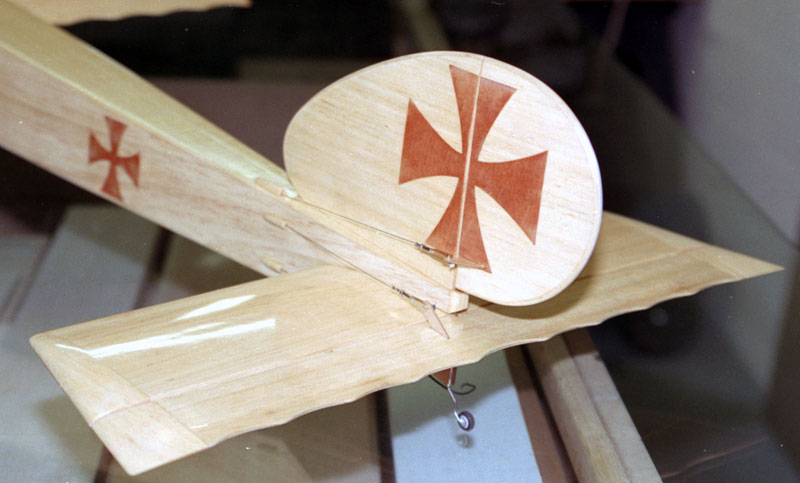
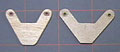
I'm building a prototype Sopwith 1-1/2 strutter and i want to make it as scale as possible. My
problem is the
pull/pull linkage.
In your article you mention
that this system needs to be a perfect parallelogram. I have somewhat
figured out the placement of the servo but I am afraid of binding.
I've attached two pics.
One of the plane so you can get a better picture of what I want to achieve and
another of my idea. Any info/link would be greatly helpful.
As long as it's close you shouldn't have
binding problems. The best way to do it is to have the holes in the servo
arm the exact same spacing as the holes in the elevator horn.
Normally what I do is choose the servo
horn I want to use and then cut a plywood elevator horn to match the hole
spacing in the servo horn.
If that won't work, say the elevator horn
spacing is a lot more than any servo arm you have, then you can make a bellcrank
from plywood and mount it in the fuselage between a couple hardwood beams going
from top to bottom of the fuselage.
Make the holes in the plywood arm the
same distance from center as the holes in the elevator horn.
Now hook up a pushrod from the servo to
the plywood arm and you're in business.
If you need the pull-pulls to come out of
the fuselage in a certain location and can't get it aligned with the arms and
horns then you can use pulleys but they tend to be a pain to set up.
Top
|
|
|
|
I'm building a rubber band to
electric Herr Fokker DVII.
In order to keep it light and
scale, I'm installing a pull/pull linkage. Can I run a single wire from
the servo to a 'Y' out to the control horns, instead of two seperate wires?
I would think there would be a
benefit to the single as it would be easier to adjust.
Example
----< this setup would be for the elevator only. Any suggestions?
The setup you propose will work
fine as long as the Y part can’t slide around on the single line part.
For example, a bad idea would be
to have one string go from the servo all the way to one horn and another string
tied around that string so it can go to the other control horn.
I would try having two
individual strings going all the way from the servo arm to both tops of the
control horns and another pair going from the other side of the servo arm to the
bottoms of both control horns. If that didn’t work, then I would move on to the
Y idea next.
If you go with the Y idea, just
make sure you tie knots or use a small ring or something so the strings can’t
slip in relation to each other. The reason being you don't want the lines
to rub and wear against each to the point of failure.
\ /
O <- metal ring
|
Top
|
|
|
|
 I
am interested in your plywood control horns used on
Rustik.
What size plywood are you using and how are you mounting them into the control
surface? I
am interested in your plywood control horns used on
Rustik.
What size plywood are you using and how are you mounting them into the control
surface?
I make the horns from the greatest thickness plywood that the
clevis will close around. For 2-56 clevises that usually means no thicker than
3/32”. I simply cut a slot through the control surface by first drilling a hole
and then using a small key-hole saw. I use small files to clean up the hole.
I use epoxy to glue the horns in after the surface is
complete. The way I do it is to put epoxy in the hole and let it soak in for a
couple minutes. Then I put in some more. I slide the control horn until it’s
almost in position and then coat it with epoxy and slide it into place slowly.
Take your time getting it positioned. While the epoxy is still wet, I use a
brush to go ahead and coat the entire horn with the same epoxy. That ends up
being the finish on the horn.
Top
|
|
|
|
I find the strip ailerons on my ARF too small (1-inch) to be
desired. I plan to modify it and put 2-inch ailerons . How should I go about
this the easiest and most economical way and increase performance?
I see 2 options:
1. Hack away the wing so it could accommodate the bigger
aileron.
2. Install the bigger aileron on the original wing recess
and build up the wing trailing edge near the fuse so the ailerons won't stick
out.
Any thoughts? The plane in question is a GP Extra 300S
40 size ARF.
Have you tried sealing the hinge line? If not you will find
that it will significantly increase the roll rate. I would do that before
anything else. Also make sure that the linkages are strong enough to prevent
the ailerons from blowing back. If that’s happening then you aren’t getting as
much throw as you think you are.
Assuming you’ve done all of that then I would go the easy
route using the second option you are considering. Make larger ailerons and
replace the originals with them. I consider this to be an inferior choice to
your first consideration, but much faster and more economical to implement.
The pure way to do it is to cut back the trailing edge such
that the wing maintains its original area with larger ailerons. If the trailing
edge is sheeted then you can draw on the covering with a sharpie marker to mark
the cut lines. Cap the trailing edge with 3/8” stock or 1/4” stock having hinge
blocks glued in place. Sand it flush with the existing wing and cover it.
If there is no trailing edge sheeting or if you will have to
cut past the sheeting to get the aileron inset properly, then you will probably
have to recover the entire wing.
Top
|
|
|
|
I am getting ready to build a Paragon sailplane. It
has 118" WS with a 1080 sq." area. Advertized flying weight is 50 oz.
The elevator is about 26" x 1-3/4" average and about 52 sq."
with 1/2" throw. The rudder is about 11-1/4" x 3-5/8 average with 1-3/4" x
1-3/4" ahead of the rear tail post, for a approximate 45 sq" overall and about
2" throws.
I was wondering if Hitec HS 85 servos would be enough for
this. I have had some say to use an HS 422 standard but it only has 4 more
ozs. of torque and I could save almost one ounce per servo using the 85s.
The only reservation I have about HS-85’s is the gear train.
If the surfaces start to flutter the servos will last all of about a half
second. I think they’re strong enough, but if you plan on doing speed runs with
this model then make sure the hinge lines are sealed and you have a very good
hinge system and linkage – don’t allow any slop in the setup. If you can do
that then I would trust the 85’s.
If you have any doubts then go to a stronger servo and accept
the weight penalty. The advantage of the standard servo (I’m guessing having
never owned one) is not the extra torque but the stronger gear train. You might
look at a mini servo that has a metal gear train as well.
Top
|
|
|
|
I'm looking for information on
installing a pull-pull system for elevator & rudder. I have never done
this. It seems simple enough but don't want to reinvent the wheel!
What if any are the pitfalls
in going this route? I want to use it on the next 40 size plane I build.
I have only recently started using
pull-pull controls regularly. In the past I only used them in scale models, but
I will be using them in more of my sport models from here on. The reason being
that they are far lighter and much more positive than a pushrod system.
There are a few gotchas but all are
easily avoided if you understand the theory. First, you have to create a perfect
parallelogram. The holes in the control horns on the control surface must be
spaced the same as on the bellcrank or servo arm to which the other end of the
cables are attached.
I make horns from plywood and glue them
into the surface. The first time I did that I was concerned about strength, but
now I know they are actually stronger than control horns that are attached to a
balsa surface.
The second gotcha is that the holes in
the control horns should be aligned with the pivot of the hinges. If the horn is
ahead of the hinges, then the line on the opposite side will tighten as the
other side is pulled.
For example, if you pull up elevator,
then the down elevator cable will tighten and cause binding or possibly even
breakage of something.
What you can do is put the center of the
holes behind the hinge pivot and the other side will slacken slightly. That is
called Ackerman.
You can buy everything you need from
Wal-Mart except the threaded studs to attach the lines to. I make my own using a
micro drill bit on a piece of threaded rod just beyond where the threads end. I
don’t know the bit number, but it’s smaller than 1/32”
The threaded studs available through the
hobby industry are over-priced, but if you don’t have a drill press and small
bits, then that’s the way to go.
If you attach directly to a servo arm,
then definitely use a ball-bearing servo. Otherwise, mount a bellcrank on a
plywood plate to attach the cables to. Use a pushrod from the servo.
I glue 2” pieces of inner nyrod in the
exits and then fish the lines back to the servos. Some people use inner nyrod
all the way back to the servo which prevents the lines from becoming twisted in
the aft fuselage.
My way is more tedious, but I prefer it
because it’s much lighter. But you do have to be careful that the lines don’t
get twisted together and that they don’t rub on anything, such as a former.
Lastly, use cable that doesn’t stretch.
On small models I use braided fishing line (not metal). It works well and is
plenty strong. On larger models, I use braided cable fishing leader. The lines
are fed through a ferrule, through the hole, back through the ferrule and looped
again through the ferrule. The ferrule is then crimped. It’s very secure.
Take the time to make sure the ferrules
are completely deburred. The last thing you want is a cable to get cut.
Take a look at the photos of the tail end
of the
Herr Piper J-3 Cub I just finished. It should make the hook up clear.
Top
|
|
|
|
When making the angle on the aileron, whether it is one or
two angles, to be joined to the aileron bay, is it always a 45 degree angle?
Does this angle ever need to be increased or decreased?
If the model is scale, then the system is set up as close as
possible to emulate the full scale plane.
Other than that, the bevel on the leading edge of the control
surface is cut to give the maximum amount of throw that you think you will ever
want.
It is often not possible to get enough throw on a 3D model by
beveling only the control surface. To get around this the mating trailing
edge of the flying surface is sometimes beveled too.
I don’t fly 3D planes so most of my designs are set up between
30° and 45° (60° – 90° total throw). Add a little bit to whatever you think
you’ll need to account for binding at the extremes.
For example, if you think you will want 45° of throw and you
cut the bevel at 45°, the control surface may start to bind at 40° due to glue
in the gap, covering or whatever. Therefore you might want to cut it at 50° so
that you can actually get 45°.
45° is a too much throw for most planes though. If you
actually look at the amount of throw recommended on planes it is almost never
even as much as 30°.
The smaller the bevel, the less opening there is between the
control surface and the flying surface which means less drag. Usually it’s not
significant enough to matter, but just something to keep in mind.
Another thing you should do is seal all hinge lines.
It will make the control surface more effective. That means that you can set up
less throw to get the same amount of response from the aircraft. Less throw =
less work for the servo, less battery drain, and more efficiency overall.
I cover hinge gap sealing on the
Hinges page.
Top
|
|
|
|
Would you tell me about setting up for different types of
throws for the elevator or rudder, etc.
If you use the outer hole in the control horn and the inner
hole of the servo arm do you get maximum or minimum movement? Do you have
an easy way the remember which is which?
What you have to keep in mind is that the servo moves fully
from one direction to the other regardless of which holes are used.
If the pushrod is farther from the center of the servo then
the pushrod moves farther.
The opposite is true of the horn on the control surface.
The farther the pushrod is from the hinge line, the less the surface
moves.
Therefore to get maximum control throw you would use the
outermost hole in the servo and the innermost hole in the control horn.
That arrangement also gives the control surface a lot of
leverage over the servo which is bad. The least amount of movement also
gives the servo the most leverage. That would be innermost hole in the
servo arm and outmost hole in the control horn.
Normally to get the throw you need you set it up somewhere in
between.
I like to set things up to use one of the outer holes in the
servo arm and use whatever hole in the control horn that gives the correct
amount of throw. Top
|
|
|
|
Having a little problem with my linkage and radio adjusting
and trim. After I test fly a new plane, 4 Star 60, I want to adjust the
linkage so that I can zero out the trim buttons on my radio (Futaba 6EXA) and
fly again.
That is where I am having a little trouble. Which way
is the best to approach this? Do I move the clevis at the control surface
in or out as needed, move the clevis up or down, or move the arm at the servo
connection?
Have looked and read quite a bit but most of what I see is
just to use the radio. That is fine but I would rather get things close
and tight on the plane then just fine tune as needed during flight and the ever
present changing conditions where I live and fly.
Any ideas or help you have would be appreciated.
It is confusing. I’ll try to explain how it works so that
maybe you’ll have a better understanding.
The hole you pick in the horn affects the control response —
not the trim. For example, if you want the elevator to be more responsive then
either go in a hole in the control horn or out a hole in the servo arm.
If you want to change the trim, then use the same holes you’ve
been using, but adjust the clevis in or out. Be sure that you have plenty of
thread going into the clevis. If you start running out at one end then adjust
the other.
If the plane needs a lot of trim and can’t get it with the
setup you have, then you may need to make a new pushrod that is cut closer to
correct length. Normally that isn’t necessary, but it’s better than having
only a couple threads in the clevis and losing the whole plane because of it.
Top
|
|
|
|
I am currently building a Sig
4 Star 40. I have never used CA Hinges before and don't want to start now.
The Last Kit I Built was the 4 Star 60 and I used
Robart 1/8 Hinge Points. They turned out great and I've gotten lots of
comments as to how good of a job I did being the first time I've used them.
My dilemma is that the control
surfaces of the smaller 4*40 are thinner than it's larger sibling and the 1/8"
points are the same thickness as the 1/8" Fin/Rudder and nearly as thick as the
3/16" Stab/Elevator and Ailerons.
The next size smaller hinge
points are the 1/2A Hinge Points and those don't seem strong enough. What
would you suggest I use?
I would either use flat, pinned
hinges such as made by Dubro or the Great Planes small hinge point. The small
hinge point by Great Planes is larger than the small Robart hinge, but smaller
than the 1/8” Robart hinge. Additionally, the Great Planes small hinge point has
a steel pin rather than plastic like the small hinge point by Robart.
Top
|
|
|
|
I am building a P-51 Mustang and plan
on using Robart Hinge Points. Your
how-to article is great, but it does
not help me do what I am trying to do.
The elevator and rudder
control surfaces on the P51 are not the same width along the length of the
surface. For example on the rudder, near the top, the hinging surface is
only 1/2" wide, while near the bottom it is a full inch or more.
How do I round this surface
off and still make the hinges look good? I want to make them look as scale
in appearance as possible.
If you are saying that there is
not enough material at the top of the rudder, then you can add filler behind the
leading edge of the rudder to capture the hinge. You can also cut some of
the barbs off the hinge, but I don’t do that unless absolutely necessary.
If that’s not what the problem
is, then maybe you can explain it in another way and perhaps send a photo or
two? I’d like to help, but I need to understand the problem.
 I have taken some pictures
and have done some research but am still not sure how I am going to do this. I have taken some pictures
and have done some research but am still not sure how I am going to do this.
On the plans, they use the
usual method for using CA hinges with both sides of the control surface beveled.
If I am using hinge points I will probably want to round the leading edge, but
this is difficult due to the odd shape. Once the rudder is rounded how to I
fill the gap between the two surfaces.
In my research I have read
about two ways, but have not seen any good pictures or how-to's. One way
was to use triangle stock on the trailing edge of the fin or the stab, but to me
this seems difficult to do with the weird shape of the rudder leading edge.
Maybe I am wrong and this is
the way to do it, I don't know. The other way was to use thin plywood to
cover the area. Once again will the plywood conform to odd shape. If
you have any ideas I would appreciate it.
I think I’m clear on what you’re
trying to do now. You want to cover the hinge line for a more scale appearance,
correct?
First, I would cut that part off
the rudder that protrudes from the front. Removing that piece will make the whole thing a
lot easier. You can glue it back on later.
The pin in the hinge point
should be back a little farther so that it is centered in the radius you sand
into the leading edge of the rudder. Depending on how thick the rudder is,
that may leave much of the forward part of the hinge unsupported.
You can add pieces of brass tube
into the rear of the fin that stick out. Glue the hinges into the tube.
That will provide a lot of support.
What I would do to cover the
hinge line is use a router to relieve an area about 3/8” wide in the sheeting at
the rear of the fin. Use pieces of 1/64” plywood or thin plastic to glue in the
relieved areas. Make the pieces wide enough to cover the hinge line.
You’ll have to mess around with it a bit to ensure the rudder can move freely.
Also, don’t forget to take into account the thickness of the finish.
One thing that I consider very
important with any model is consistency throughout the project. A lot of guys
want to deck out their first scale model, but aren’t really ready to build the
model at all. Then when things start not working out they are disappointed with
the project overall or put it aside or sell it.
I do not want to discourage you,
but advise that maybe you build the model per the plan just to get a feel for it
and gain experience. You can always build another P-51 later. The
reason I mention consistency is that I’ve seen a several scale models that had
lots of detail in some areas and no detail in others. Those models end up
looking kind of odd.
My point being that whatever
level of detail you decide you want, you should commit to doing to the entire
model. Don’t rivet the fuselage if you’re not going to rivet the wing. That’s
just one way of looking at it of course. You may think that it’s good practice
and who cares if the whole model is riveted. I can’t really fault that
line of thinking. Top
|
|
|
|
Being fairly new to the model
scene in the UK I am bewildered by the sheer quantity of servos available on the
market. The prices vary from one extreme to another.
The three areas which seem to
have a bearing on price are the Torque, Speed and construction i.e. metal
bearings, plastic gears, metal gears and now more recently digital servos.
Where do I start?
There seems to be no real
guidance as to what you should need for what job. If a servo fails in
flight it would be 'goodnight Vienna'.
Do you have any advice or rule
of thumb to help me select the right type of servo for the job? How do you
calculated the forces being applied to a control surface during flight and then
relate it back to the torque characteristics of the servo? So many
questions and a BIG EXPENSIVE MINEFIELD. Help please.
I asked this exact same question at RC Universe and nobody
could give me solid numbers as far as torque to surface area. A slower
flying aircraft can use a smaller servo on a surface than one that is faster due
to loads on the surface.
You would have to work out a formula that includes all the
following information:
-
Airfoil
-
Overall Chord
-
Control Surface Span
-
Control Surface Chord
-
Flight Velocity (air speed)
-
Control Surface deflection
-
Hinge Line location in relation to the airfoil's neutral
point
-
Probably other stuff that I haven't thought of.
The real answer is that a generic formula just doesn't exist
as far as I know. What you have to do is use your experience to choose
servos. As a beginner, you don't have that experience yet, so best to ask
guys in your club about your specific application.
When in doubt, use a stronger
servo, or ease your aircraft into maneuvers so you don’t kill your servos and
crash your plane. If the servo seems to be unable to hold the surface, then go
to a larger servo.
Today’s servos package much more torque and speed in a smaller
package than they used to. For example, a Hitec HS-85 mini servo has as much
torque and is faster than most standard servos that come with a radio control
set, yet they are smaller and lighter.
Top
|
|
|
|
I am just beginning to get into designing R/C airplanes.
I had a question about control surfaces. How do you go about deciding
where to put your control surfaces and the dimensions of them?
Also, what is a good way to find out if the servos that you
are using are capable of producing enough torque for your control surfaces?
Are there any simple calculations that you know of? If not, what factors
should I consider or am looking at to determine this?
I’ve read this e-mail a few times and unfortunately, my answer
for you isn’t an answer. For new designs, I generally run the numbers of
standard design parameters and then adjust until the plane is more what I’m
looking for. For example, if I want a plane that is aerobatic, yet smooth, I’ll
start with a standard aerobatic design and lengthen the moments.
Once I have an outline, I start sketching in the control
surfaces. Again, I use "standard" sizes and then adjust until it looks right.
Aerodynamics tend to break down when building smaller aircraft, such as our
models.
Now if I’m building another prototype of a plane I’ve already
built, then I make changes based on observed behaviors of the model after ruling
out everything possible in the prototype. For example, an inability to spin may
be many things, but most of them can be ruled out in the prototype. Things like
the center of gravity or fin and rudder size can easily be changed.
There are just too many different type aircraft and different
behaviors to give a solid set of numbers that will work. A lot depends on how
you think a particular design should fly.
There are a few books on the market that discuss the
aerodynamics of model aircraft in detail. Unfortunately, they are way over my
head so they aren’t much use to me. The one I have is Martin Simon’s book,
Model Aircraft Aerodynamics. It covers a lot of theory in simple terms, but
then goes into aerodynamics terms I don’t know how to use. What that means is I
can get some rule-of-thumb generalities from the book, such as efficient wing
shapes for various aircraft types which is helpful.
The bottom line is that I have to go with my experience, which
I have lots of, as well as just standing back and looking at a design and
deciding if it looks right or not. I’ve found that a design that looks right –
is.
Last thing – this may seem kind of strange, but I imagine the
plane flying. Sometimes a design that looks like it will fly right, doesn’t
look right in my mind when I try to “fly” it in a certain manner. I adjust the
design until it looks like it will fly as I imagine it to and I’m almost always
right. I wonder how many designs came about that way. For me, it’s almost
everything I’ve ever designed – especially those I put on paper first rather
than made up as I was building.
Top
|
|
|
|
I had two of four CA hinges fail on my Kadet PT-40's
elevator.
I cut the old hinges and thought to clean out the old hinge
slots and install pinned hinges. Of course, the elevator now binds! My
idea now is to cut through the new hinges and make
Monokote hinges. I read your technique - good info.
My question is - what do you think about using self-adhesive
trim sheet instead of regular iron on film? Do you recommend another solution to
my dilemma? Thanks for the help.
I would not use self-adhesive film for hinges. I'm not
sure why, but it just doesn't seem like a good choice.
What I would do in this situation is remove the elevator
completely and replace all the hinges with Dubro standard pinned hinges (flat).
I would not necessarily attempt to put the hinges back in the
original locations though. It will probably be easier to cut new slots near the
old hinges.
If you've never done any hinging before, maybe you can find
someone in your club with some experience and have them show you how to do it
properly.
Top
|
|
|
|
I installed and promptly removed the
CA hinges on 1/2 of my H9 Taylorcraft wing and aileron leaving some
unsightly holes (primarily on the wing TE). I plan on installing Robart
hinge points via your
tutorials.
Upon closer inspection I noticed that the wing
TE of the ARF is a piece of 1/8" balsa TE with 1/8" backer pieces. The
backers do not span the distance between the
ribs only long enough for CA hinge width.
What should I do? Cut out TE and backers replace with
some deeper filler pieces and a new TE? What about the virgin wing?
Is 1/4" of soft balsa enough for a 1/4 scale gas burner?
I think I’m kind of clear on what you’re doing. The filler
pieces do not need to span the distance from rib to rib. About 3/4” wide is
good enough if you can hit the middle of it (more or less) when you drill for
the Hinge Points.
However, the filler piece should be deep enough to completely
enclose the hinge. If you choose to use hinge points, I do not think 1/4” fill
will be enough. The reason being that when you put glue in the hole and then
insert the hinge, a lot of glue will be pushed out the other side of the hole if
it’s open. For that reason, I like to make sure the filler piece more than
encloses the hinge and then I take care not to drill all the way through it.
I’m assuming this is an ARF and you’d have to cut away
covering to get inside the wing.
You could use flat hinges and then pin them. I would trust
that and then you wouldn’t have to do surgery. That is probably the route I
would take unless the wing is already open and I can get to the trailing edge to
add more material.
Also, you didn’t mention how many hinges you are using. I
would space them so that you have at least 4 per aileron, 3 per elevator half, 4
for the rudder and the hinges no more than 5-6” apart. What that means is that
you might need more hinges than the numbers I mentioned if the control surface
is very long.
Top
|
|
|
|
I wanted to know if you think that it is necessary to purchase a
drill press. I have been doing a lot of reading on line and I am not sure.
I have been using CA hinges and the Great Planes Hinge
Machine. After reading your article on
Robart Hinges I am not sure what to use.
Do you think that I should try the Robart Hinges out and do
you think since I have not worked with then that I will be successful with them?
I do not use CA (cyanoacrylate)
hinges ever. I just do not like them. Robart hinges are my favorites
by far, but I still use flat, pinned hinges on surfaces that taper so much that
a hinge point would go through the outside or a surface that is so thin that
even the smallest Hinge Point would be difficult to install.
A drill press is absolutely unnecessary. It makes the
job easier and faster, but the Robart drill guide works very well. However, I
suggest that you do not use a power tool, such as a drill or a Dremel with the
Robart guide. Use a pin vise or simply twist the bit with your fingers.
You want to go slowly so you can stop and adjust if the bit starts to go into
the surface at an incorrect angle.
Also, I suggest you practice on some scraps first. There
is nothing like experience to teach you how things work. Never attempt new
techniques on your model with practicing first!
The fixtures will not help much with the wing.
Read my how-to concerning
building a wing and follow the directions that come with the kit carefully.
Measure everything and do not put glue on any part until you are absolutely
certain you are gluing it in properly. I strongly advocate using
Carpenter's glue because it gives you time to work and adjust things.
CA simply sets up too fast and if you make a mistake it is a real pain to fix.
Top
|
|
|
|
Do you have any sketches, or detailed steps, that
you would be willing to share with me about the mechanical flaperon set up?
I only have a 4 channel radio/7 channel receiver. Thank you so much.
You need at least a 5-channel transmitter to use flaperons
unless you don’t use one of the other channels – such as the rudder. I don’t
suggest you do that. Flaperons require either a computer mix in the
transmitter, an after-market device that plugs into the receiver or a
mechanical system, such as a sliding tray or the Dubro mixer that attaches to a
servo arm.
I have a computer transmitter, so that’s what I use.
Unfortunately, I don’t have any diagrams of a mechanical mixer, but I’ve seen
diagrams in various places. Try searching
RC Universe or the
internet using the term “mechanical mixer” AND "radio control."
Top
|
|
|
|
|
|
|
|
Back to Mail and FAQ
Airfield Models Home |
|
|
|
Copyright © 2004-2007 Paul K.
Johnson |
|
|