Airfield Models - How To

Make a Set of Ribs for a Constant Chord Wing

December 18, 2021


Home
About
What's New
History
Models Gallery
Model Building Safety
Articles
Mail & FAQ
Site Map
Site Feedback
Contact
Add to Favorites
Comments
Search Airfield Models

Back to How-To Articles


Airfield Models (http://www.airfieldmodels.com/)How to Make a Set of Ribs for a Constant Chord Wing

The simplest type of wing to build from scratch is one having a constant chord planform.

A rib template can be made from a hard material such as thin plywood or Formica.  A hobby knife is used to cut around the pattern to make as many ribs as needed.

Alternatively, rib blanks can also be stacked and cut using a power tool such as a scroll or band saw.  The latter methods are usually the fastest, but not always the best.

The rib blanks for the stack are usually rectangular which means a lot of wood goes to waste.  Additionally the stack of blanks is tall and narrow and spongy which means it can flex or distort.  I have run into this problem more often than not.  The end result is a lot of wasted wood and an unusable set of ribs.  My preferred method is to cut the ribs around the pattern.  It takes more time, but has given me a better result.

I will use a scroll saw to cut short stacks of ribs.  I usually stack the ribs for the wing center section to trim off some of the rib to account for the sheeting after cutting and sanding the rib blanks. I don't stack ribs more than 1/2" high to cut with the saw for the reason mentioned above.

Modify individual ribs or matched pairs as necessary to include cut-outs for landing gear blocks, holes for servo leads and pushrods, etc.

The first step is to plot an airfoil from which the rib pattern is created.  Add details to the drawing such as the leading edge, trailing edge, spars and sheeting.  It is helpful to draw in other details such as the holes for servo leads even if they will not be in every rib.

It is generally wise to place the main spars at the thickest section of the airfoil.  The farther the spars are spaced apart, the stronger the wing will be.

Also see


The set of ribs presented here were used to build the wing for Rustik.  I had only a rough idea what the wingspan would be at the time I cut these ribs.  I cut some extra rib blanks to give myself flexibility.

I do not go along with the current design philosophy made popular by 3D aircraft of spacing ribs 7" apart.  I like ribs spaced no more than 2-1/2" apart and even closer when the wing will be fully sheeted.

This wing will be fully sheeted, have no dihedral and be constructed in one piece.  The spars and sheeting will be full span and shear webs will be used.  No dihedral bracing will be necessary as the wing will be adequately strong without it.  Four servos will be used in the wing (2 ea. flaps and ailerons).  The control surfaces will be built up separately.

These ribs have large internal cut-outs to save weight and allow passage of servo leads.  The cut-outs are optional if you build a wing using torque-rod driven ailerons.

Always drill a hole in every rib to allow the wing to vent.  The more ribs there are the more venting there should be.  You may need to drill additional holes if you can't make the hole larger.

Drill a hole in both the forward and aft portions of the rib if the wing has shear webs.  Venting is important to prevent your wing from exploding from sudden changes in atmospheric pressure while flying.  I have never seen it happen but I have heard of it happening particularly among sailplanes that fly at higher altitudes.

Glue the rib pattern to a piece of plywood.

1/16" aircraft plywood is used for the master pattern.  Any thin, hard material will work as long as you can shape it.

Draw a centerline on the hard pattern using an ink pen.  Attach the paper pattern to the plywood using spray glue being sure to align the centerlines.

Cut out the pattern and sand the outline to final shape. The pattern is cut slightly over-size and then carefully sanded to shape.  The pattern should be as stable as possible.  Interior cut-outs will be made after the ribs are cut.

Note that the spars are located at the thickest point of the wing.

Glue sandpaper to the back of pattern to prevent slippage while cutting.

Sandpaper is spray glued to the back of the pattern to prevent it from slipping when cutting the ribs.

Cut the rib blanks using the template. The ribs are cut from several sheets of lightweight contest balsa.  I used a hobby knife to cut around the plywood pattern.

The spar cut-outs are deliberately undersize so that they can be sanded to a perfect fit.

The ribs are more flexible and fragile with the internal cut-outs so I will make those after the ribs are sanded to shape.

Nail blanks together. Square the stack of ribs and pin or nail them together so they can be gang-sanded.

T-Pins are not long enough in this case so I used small nails from both sides of the stack.  The nails are located within the cut-outs that will be made later.  Be sure to use enough pins or nails so the stack can not shift while sanding.

Sand blanks to shape. The ribs have been sanded to a uniform shape using a small sanding block (not shown).  The small hardwood sanding block shown here was used to finish the spar cut-outs.  Scrap pieces of spar material are used to check the progress during sanding.

It should be obvious that the spar notches in the ribs should be sanded to match the spars.  Don't sand the scrap spars to match the spar notches.

Take careful measurements to ensure the stack of ribs is as uniform as possible.  A diagonal line drawn across the ribs indicates the order in which the ribs are stacked as well as which side is up.

Do not remove the pins until you are absolutely satisfied with the rib set.

Remove interior portions of ribs. Optional Make the internal cut-outs.  This operation does not need to be as precise as the outline so the ribs are divided into two stacks.  A scroll saw speeds things up.

Make the cut-out in the plywood pattern.  The outline of the cut-out is traced on the topmost rib. Holes are drilled to allow passage of the scroll saw blade.

If you do not own a scroll saw you can use the plywood pattern and a hobby knife to make the cut-outs.  Normally I drill the corners with the ribs stacked and then use a knife and straight-edge to connect the corners of each rib individually.

The completed rib set. The completed rib set.  The three ribs at the bottom are cut from thicker stock.  The center of these three ribs is 1/4" balsa and will be in the center of the wing.

The ribs on either side of the center rib are 3/16" balsa and will be positioned directly over the wing saddles.  These two ribs must fully support the wing so the cut-out is smaller to ensure the ribs will have adequate strength.

On the right is the plywood pattern.

In some cases additional holes or cut-outs will be needed.  For example, the center ribs may need to be cut in half to allow the use of dihedral braces.  Select the appropriate ribs from their position in the stack taking right and left wing panels into account.  Make any modifications necessary.  When the ribs are completed put them in a safe place until you need them.

Always save your templates. People who throw their templates away, crash their planes and need to make new ribs.


Lightening Wing Ribs

I received an e-mail from a person who wanted more information about the strength of a rib that had large internal sections removed.  It is a legitimate concern simply because nobody wants to build a model that self-destructs in flight.

I have used ribs similar to this in several of my models and have had no problems.  To date not a single rib has broken in flight or from handling.  However, you do have to be careful when handling the wing.  For example the ribs used for Great Gonzo have a 1/4" outline.  The wing must be lifted by grasping the spars or the center section sheeting.  There is a good possibility that the rib would break if the wing were lifted by supporting it under a rib.

I have had to repair Great Gonzo three times due to damage that occurred on the ground on exceptionally windy days.  The first damage was caused when Great Gonzo blew off a table at the field and fell several feet to the ground.  It flipped over in the air and landed upside-down directly on the wing which flexed and tossed the model back into the air.  Damage incurred was a broken leading edge near the wing root.

The other two times both occurred during take-off.  Great Gonzo was blown over when it turned cross-wind (pilot error) and cart-wheeled several times.  The first time this happened a main spar was broken as well as the leading edge.  The second time the tail end of the fuselage had a minor crack and the leading edge of the wing broke again.  Notably, no wing ribs were broken in any of these incidents.

My Stik 30 has smaller cut-outs because the model was designed for higher performance.  As I mentioned on the My Stik 30 page, the ailerons can deflect up to 45° in each direction on high rates.  The roll rate is so fast I can not count them.  Additionally, when the Webra .32 was mounted on it I put the model in several full-throttle, terminal-velocity dives of several hundred feet.  The airframe had no problems with this.

My Stik 30 uses the same wing that was on the first version that I crashed on take-off at full throttle.  That crash was due to putting a wing tip in the ground and cart-wheeling the plane (my favorite way to break airplanes apparently) across the field.

The wing was subjected to a significant torsion load but the only damage to it were a couple dents in the wing tips and a broken turbulator spar.  None of the ribs were damaged.  The fuselage was totaled.

As far as weight savings goes, it is all relative.  If you are trying to shave every ounce of weight from your aircraft, then the effort to remove weight from the ribs is worth it.  On the other hand, the weight savings of the ribs alone probably is only an ounce or so for a .40 size ship assuming the use of contest balsa.  If the ribs are made from heavier wood then the weight-savings will be greater.

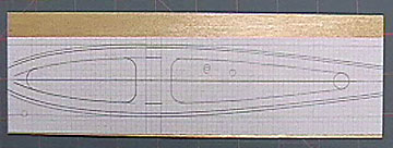
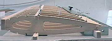
The following images show the wing construction of My Stik 30.  Again, this wing survived a full throttle cartwheel across the field and is still in use.

A set of ribs. 
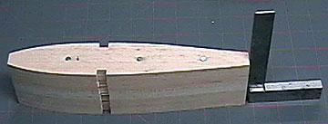
My Stik 30's wing has turbulators on the top and bottom of the forward portion of the wing and cap strips on the aft portion of the wing.
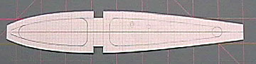
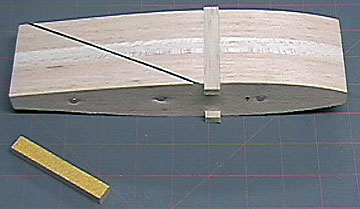
A constant chord wing under construction.

Note the shallow grooves in the spars (a little deeper than 1/64").  These make it very easy to align the shear webs between the spars and provide additional gluing area.  The grooves can be cut on a table saw or router table.

The black items you see on the T-pins are called Pin Clamps and are manufactured by Rocket City.

A constant chord wing under construction.

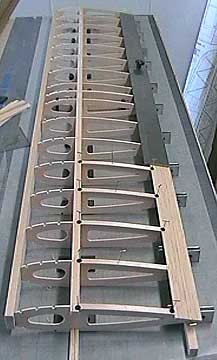
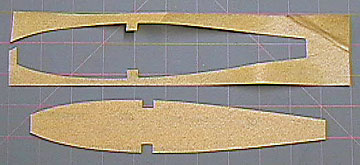
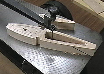
Another view of the wing under construction.  The wing is light and strong.  There are twelve one-piece, full-span wood strips in the construction:

  • 3/8" x 3/4" Leading edge (1)

  • 1/8" square Turbulators (6)

  • 1/4" x 3/8" Main Spars (2)

  • 1/16" x 1-1/2" Trailing edge sheet (2)

  • 3/8" square Trailing edge (1)
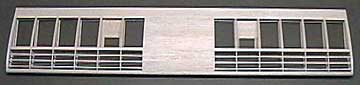
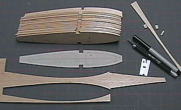
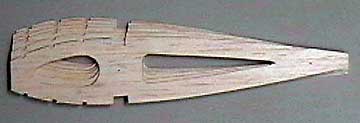
The completed My Stik 30 wing.

The completed wing.


Previous —
Next —

How-To Articles for Model Builders
How to Make a Set of Ribs for a Tapered Wing

Comments about this article


Back to How-To's
Airfield Models Home


Copyright © 2003 Paul K. Johnson