![]()
|
|
|
|
|
|
|
|
|
|
|
|
|
|
|
|
|
About the Kit
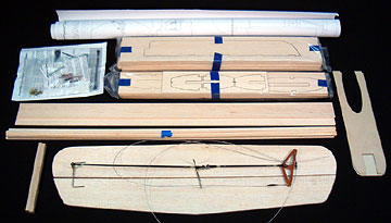
This DoodleBug and a couple others are currently being kitted by Control-Line-Models owned by John Lowry out in Oklahoma (Link removed due to company now defunct). He also kits several other control line models. In fact, this model was built for John so you may see photos of it on the control-line-models site. The kit is well done and mostly complete. This kit was supplied without gear because I was asked to make one from aluminum. The control system in the above photo is custom and was supplied by Tom's Building Service. More about the control system to come... The wood is laser cut. Parts fit is excellent and match the CAD drawn plans very well. No instructions are included with the kit, but the model is simple and the plans are clear and easy to follow (unless you're like me and make bad assumptions without consulting the plans). There were a couple problems with the kit but nothing really major. First, all the sheets and sticks for the wing were about 1/8" too short. That could be due to the plans changing size due to the climate or possibly just a mistake by the manufacturer. The tip ribs could be moved in slightly which would not make a noticeable difference in the model. I elected to replace the sheets and sticks and put the supplied wood in my stock. The hardwood motor mounts were also too short so I replaced them as well. The two fins were extremely hard balsa and were heavy. I was very concerned about the balance of this model due to the huge stabilizer/elevator so I replaced the fins as well. The rest of the wood was good quality and appropriate for its application. The hardware pack is minimal. It consists of a Sig bellcrank, landing gear and straps to hold it on. No other hardware is supplied. You will need a fuel tank, a couple J-bolts to hold it on, bolts to mount the engine, a pair of control horns, two pushrods, four ball-links, wheels, wheel collars, lead-outs and a lead-out guide. I've had the itch to get back into some control line flying so I ordered one of these kits for myself. I hope to have mine in the air soon.
|
|
|
ConstructionThis is a relatively simple model that shouldn't present any difficulties to a person who has built a kit or two. Fuselage
A plywood doubler is glued on to each side and that's it for the fuselage construction other than sanding and drilling holes for the gear, engine and tank mount. As I mentioned, I was concerned about the model being tail-heavy so I sanded as much wood from the back end as possible. I also sanded the fins as thin as I felt I could get away with. The kit also includes two aluminum plates to space the engine and prevent the bottom of the engine from bottoming against the plywood doubler. These must be drilled to match the engine mounting holes. Wing
The kit goes the more conventional route of just having a single stick for the leading edge. The notches aren't utilized. I placed a 1/8" carbon fiber tube in the notches to help me keep the wing straight while I was building it. I removed the tube before gluing the leading edge in place. The only "problem" with building this wing is when sanding the leading edge of the ribs flat for the leading edge to be glued on. The ribs pointed away from the direction I sanded tend to deflect instead of being sanded. The ribs pointed against the direction I sanded tended to chatter. Some of the ribs meet at the leading edge so I glued them to minimize this tendency. I also attempted something I've never done before. I added cap strips to the ribs before the leading edge was glued in place thinking they would stiffen the ribs somewhat to make sanding the leading edge of the ribs more effective. While it worked regarding the sanding, it was also more difficult to glue down the cap strips than it would have been to sand the rib leading edges. After gluing on the first couple caps, I decided to just sand a couple ribs at a time using an up and down motion rather than a spanwise motion. You don't have to sand the leading edge of the ribs at all, but the plane will look better if you do and it will give more gluing surface to hold the leading edge on. The plans indicate that a tip weight box is built between the last two ribs of the right wing panel. No drawings or instructions are provided so you're on your own here. Do yourself a favor and build the box before you glue on the cap strips. It will be much easier that way. John indicted to me that the model needs at least 1-1/2 ounces of tip weight so I epoxied that amount of lead shot into the box while I was building. The box I built could easily hold another 6 ounces of lead which is tons more than will actually be needed. the plywood cover is held in place with four #1 sheet metal screws and washers. The wing tips are three layers laminated together. Each layer is two pieces that can either be joined before they are laminated or at the same time as they are laminated. There are blocks added to the wing tip at the leading edge but they don't quite come up to the outline of the rib so I added a piece of scrap to finish them off. The trailing edge sheeting is wider than the tip at the trailing edge so I trimmed the sheeting to match the tip. I thought it made the wing look better and it's more than strong enough, so losing a little sheeting didn't hurt anything. There are shear webs between the trailing edge sheeting in the areas where there is the least rib support. I went ahead and added webs for the full span. One thing that concerned me was the lack of support for the wing tips between the leading and trailing edge. My experience with the last DoodleBug that I built was that I really had to pull hard on the covering to get it to conform to the thick wing tips. The same was true for this wing, but the tips didn't bow in like I thought they would. Control System
The bellcrank is phenolic. Overall it's a monster system that should survive anything short of a nuclear blast. I still managed to find a way to foul it up though. By not consulting the plan before installing the system, I installed it on the wrong side of the model. When I started hinging the flaps, I realized the flap horn had been brazed backwards. After freaking out for a suitable period of time I realized the horn was fine — it was me that was backwards.
For reasons I can't remember now, I had to change the way the bellcrank mounted when I moved it over. I had originally cut spacers from an aluminum bushing I had. When I moved the bellcrank I used bearings from the inside of a Zip disk instead. I played around with it for a while before installing it and was very pleased with how it worked. The Zip disk bearings have a coating on them which allows the bellcranks to rotate smoothly. The bearings are large in diameter and completely prevent the bellcrank from rocking. Note that no materials for mounting the bellcrank are included in the kit. All you need is a small amount of 1/8" aircraft plywood. Learning from my mistakes, here's what I suggest you do. Cut four platforms the shape shown on the plan. Measure the distance between the spars. Measure the distance top to bottom of your bellcrank. Subtract 1/4" (the thickness of two plywood plates) and divide the number you have left by two. That's how thick the balsa spacers between the spars and the mounting plates should be.
You'll probably have to cut away some of the plywood platforms to get full movement without interference. I also had to open up the cut-outs in the ribs to allow free movement of the lead outs. In fact, there is no reason for the rib cut-outs to be so narrow. A lot more balsa can be removed from all the ribs which is what I plan to do when I build mine. Also note that there is a left and right flap. The elevator pushrod is connected to the flap pushrod. The left flap has a cut-out to clear the elevator pushrod. I used five Dubro medium hinges to hinge each flap. Notches are laser cut into the flaps where the hinges go. The flap horn and elevator horn have brass bushings on them which I cut away carefully using an emery wheel in a Dremel tool. Stabilizer and ElevatorThese two pieces are huge! The balsa included in the kit was nicely selected having appropriate grain and weight. Both pieces were about as flat as a sheet this size is going to be. They weren't bowed, cupped or warped. About all you have to do is hinge them and install the control horn. I inset the wire joiner and used ten Great Planes hinge points which are larger than the Robart small hinge points (having plastic hinge pins) and the standard Robart hinge points which would have been too large. The Great Planes hinge points have a metal hinge pin. I sanded the elevator and stabilizer for a very long time to remove as much weight as possible. I left just enough thickness so the hinges had a little material on top and bottom and wouldn't break through. The only other work necessary is sanding the edges straight and rounding over the leading edges. I don't think it would be a bad idea to taper the elevator. This model did come in tail heavy so removing that much more material would be helpful.
|
|
|
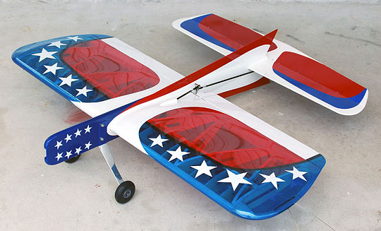
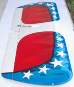
FinishingWhen I asked how John wanted the model finished he said, "I'm not telling
you to make a flag, but I want it transparent red, white and blue with stars
— a real eye-popper."
The fuselage was fiberglassed using .75 ounce glass cloth. The plan indicates the use of leather fillets which I haven't heard good things about. I wasn't about to experiment with something I had no idea how to use on somebody else's model, so I made epoxy and micro-balloon wing and stabilizer fillets after glassing the fuselage. Actually, the wing fillets have more chopped fiberglass than micro-balloons to strengthen them since the would be very vulnerable until the wing is glued in. Although the plan indicates the fillets are optional, I suggest that you make them to provide more gluing area for the wing.
Even so, when I assembled the model the tail dropped pretty hard. The engine was held in place with a couple plastic clamps. The elevator pushrod wasn't connected which would make the condition worse. No muffler was on the engine so that will help, but the model will still need a Higley heavy hub or some other type of weight up front to balance it. For my DoodleBug I'm strongly considering using a built up stabilizer using ribs and 1/32" contest balsa sheeting to not only give it an airfoil but to reduce the weight. I may use a .40 four-stroke as well. I'll let you know when I get there. Also see
|
|
|
|
|
|
|
|
|
Copyright © 2006 Paul K. Johnson
|
|


 As
far as I know, the DoodleBug 580F is the largest and most advanced of Bill
Netzeband's DoodleBug designs. If you've built any of his others then
this kit will seem very familiar. I built the
As
far as I know, the DoodleBug 580F is the largest and most advanced of Bill
Netzeband's DoodleBug designs. If you've built any of his others then
this kit will seem very familiar. I built the
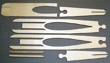 The
fuselage consists of four laser cut balsa pieces that make two sides to be
laminated together. Hardwood motor mounts fit into pre-cut areas.
The
fuselage consists of four laser cut balsa pieces that make two sides to be
laminated together. Hardwood motor mounts fit into pre-cut areas.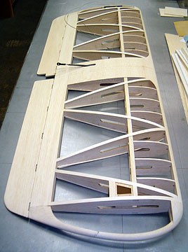 The wing is the same
diagonal rib construction as all other DoodleBugs. It is simple to
build, light and very rigid. The ribs have a 1/8" square cut-out in
the leading edge. The plans indicate that a 1/8" sheet is glued into
these notches and then a stick is glued on the top and bottom to create the
full leading edge.
The wing is the same
diagonal rib construction as all other DoodleBugs. It is simple to
build, light and very rigid. The ribs have a 1/8" square cut-out in
the leading edge. The plans indicate that a 1/8" sheet is glued into
these notches and then a stick is glued on the top and bottom to create the
full leading edge.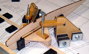 As I mentioned, the
control system installed in this model is not what comes in the kit.
It is a system made by Tom's Building Service consisting of U-shaped wires
having brass bearings and steel horns brazed on. The pushrods are
carbon fiber with 4-40 rod ends and 4-40 helicopter style ball links.
The carbon fiber rods are wrapped with what looks like Kevlar thread and
coated with glue. They are very nicely done.
As I mentioned, the
control system installed in this model is not what comes in the kit.
It is a system made by Tom's Building Service consisting of U-shaped wires
having brass bearings and steel horns brazed on. The pushrods are
carbon fiber with 4-40 rod ends and 4-40 helicopter style ball links.
The carbon fiber rods are wrapped with what looks like Kevlar thread and
coated with glue. They are very nicely done.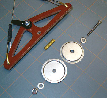 The nice bellcrank
mounts I built had to be hacked up so that I could move the bellcrank to the
left side of the plane (as indicated on the plan).
The nice bellcrank
mounts I built had to be hacked up so that I could move the bellcrank to the
left side of the plane (as indicated on the plan). 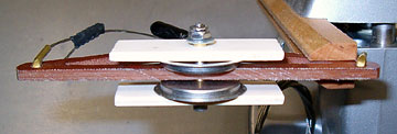 Assemble the whole
thing outside the model and then insert it into the wing. Adjust as
necessary before gluing it all in place. I strongly suggest that you
use
Assemble the whole
thing outside the model and then insert it into the wing. Adjust as
necessary before gluing it all in place. I strongly suggest that you
use
 The wing is covered
with Oracover Lite plastic film (
The wing is covered
with Oracover Lite plastic film (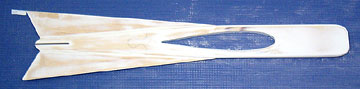 The tail surfaces
were also glassed. The fuselage and tail surfaces were primed and
painted with
The tail surfaces
were also glassed. The fuselage and tail surfaces were primed and
painted with