 |
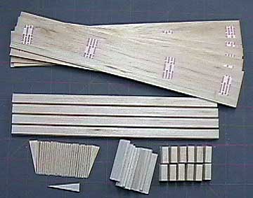
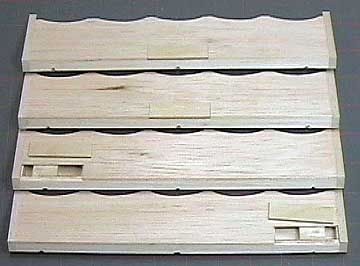
Parts for each of the flaps and ailerons.
Common double-stick cellophane tape is used to hold the skins together
for shaping. The only parts not shown here are the plywood
control
horn mounts. The
leading edges will
be prepared for hinges as shown here
before beginning assembly. In the
lower left is the plywood
template used to cut the
ribs. |
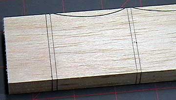 |
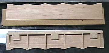
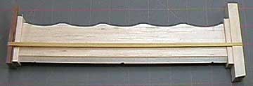
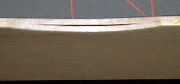
The balsa wood
skins have been taped together and
squared. Lines have been drawn on the leading edge to be
transferred to the inside of the skin after they are separated.
The scallops are cut roughly to shape using a
scroll saw and then sanded
using a drum in a moto-tool or sandpaper wrapped around a bottle.
If you
use double-stick tape on thin wood then be gentle when peeling the wood
apart. |
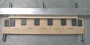 |
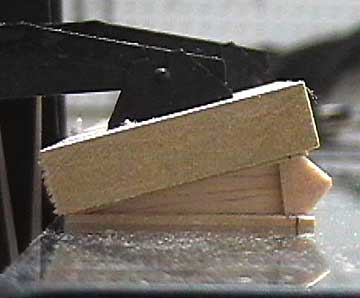
A skin is placed on a flat building board. The end ribs are carefully positioned over a
line drawn parallel to and spaced back from the front edge of the lower
skin to allow for the leading edge to be glued inside the skin as can be
seen in later photos. The tip
ribs establish a straight line for the leading edge.
A straightedge is used to ensure the
leading edge is absolutely straight. A piece of hardwood
provides a stop at the trailing edge so the leading edge remains under
clamping pressure. |
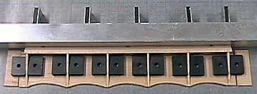 |
The remaining ribs are glued in place and
allowed to dry. |
 |
The
hinge support blocks are centered behind
the pre-drilled hinge holes and glued in place. |
 |
After a careful sanding to get the ribs and
leading edge flush the upper skin is glued in place. |
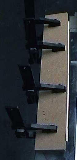 |
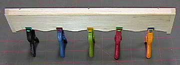
A scrap of MDF is used to clamp
the upper skin in place on my glass workbench. If the flaps and
ailerons are not straight the airplane will never fly straight. |
 |
Another view of the upper skin being glued
in place. Notice the skins and leading edge have been left over
size. Again, Hayes clamps are being
used. The jaws swivel and are perfect for situations like this. |
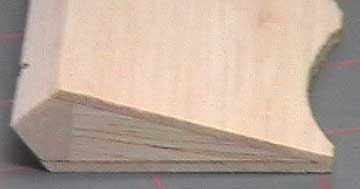 |
When laying out the flaps and ailerons I
took into account the thickness of the end cap. I really don't
like the unfinished look shown here and always cap these parts.
It is not as important when an opaque finish
will be used, but it is more difficult to get iron-on coverings to stick
to end grain so I always use caps regardless of the finish. |
 |
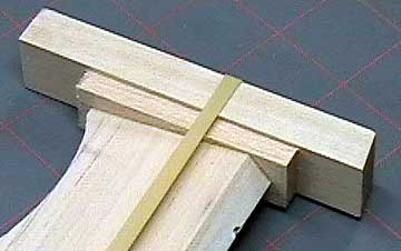
Two scraps of hardwood and a rubber band are
used to clamp the end caps in place. To prevent the control
surface from
bowing under pressure I even up the tension by adjusting
the band. The band was removed after about 15 minutes to relieve
pressure on the control surface. |
 |
Another view of the end cap being glued and
clamped in place. After the caps dry the
control surfaces will be
rough sanded. |
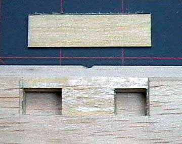 |
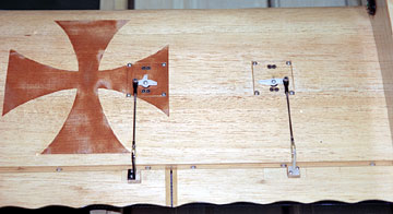
The skin is cut out to receive 1/16" plywood
control horn mounts. The
servos are positioned in the wing so that
the control horn is located close to a hinge. This also means that
there is a hinge support block in the area which provides a solid anchor
for the plywood plate. Due to the
size of the control surface and the amount of taper, the horn will be
mounted well behind the hinge line. After the surface is
fiberglassed a hardwood wedge will be
epoxied onto the plywood plate to
rotate the horn forward. |
 |
All four control surfaces ready to have the
control horn mounts glued in place. The mounts were glued in place
using Carpenter's glue and then clamped back to the table with Hayes
clamps as shown above. The flaps
have the control horns mounted in the middle and the ailerons have the
control horns mounted on the inboard end. This decision was made
to reduce the length of the servo extensions as well as keep weight as
inboard as possible. Weight towards the tips reduces
roll
response. |
 |
One small detail remains. Due to the
taper of the control surface the scallops create areas where the
trailing edge of the skins do not meet. |
 |
I squeezed a small amount of Carpenter's
glue in the joint and used small spring clamps to hold the skins
together until the glue dried. You
may have noticed that the scallops have sharp corners. I left them
like this because the square edge between scallops provides a place to
measure from. Also this area is prone to being dinged during
handling. I rounded these edges during finish sanding. |
 |
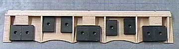
The flaps and ailerons mounted to the finished wing. Put the control surfaces in a safe place until it comes time to apply the
finish.
For now the wing will be set aside while the
fuselage is constructed. The wing will be needed without the wing tips
attached to use as a pattern for the
wing saddles
on the
fuselage sides.
|

