Airfield Models - Wing Construction Example

Make Servo Mounts and Hatches for a Model Airplane Wing

December 18, 2021


Home
About
What's New
History
Models Gallery
Model Building Safety
Articles
Mail & FAQ
Site Map
Site Feedback
Contact
Add to Favorites
Comments
Search Airfield Models

Back to Wing Construction Example


Airfield Models (http://www.airfieldmodels.com/)Make Servo Mounts and Hatches for a Model Aircraft Wing

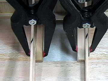
I have stopped timing the wing construction at this point.  I worked on the hatches at various stages over a couple of days and lost track of time so often that I couldn't give an accurate estimate.  My intention was to show that building time is not dependent on glue.  It is mostly in parts fabrication, dry-fitting and other preparation.

The hatches turned out to be more complicated than anticipated.  I originally planned to use Futaba S3002 metal-gear, mini servos for the flaps and ailerons.  These servos have (depending on who's specs you believe) 52 inch-ounces of torque.  They also weigh (again, specs from different sources vary) 1.27 ounces each.  That is over 5 ounces in servos alone
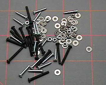
 not counting the hardware, extensions etc.  It also is a combined total of 208 ounce-inches of torque for the ailerons on a .40 size aircraft.

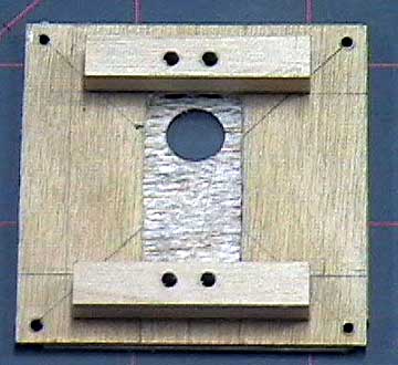
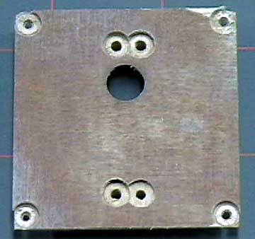
Because of the bearing in the top of these servos, the arm is slightly higher than a non-bearing servo.  The hatch cover requires a hole that will allow the portion of the servo case around the output shaft to go through it.

I ended up using JR C341 mini servos that do not have a bearing.  These are rated at 31 ounce-inches of torque and weigh .67 ounces — roughly half 
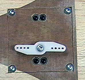
as much as the Futaba servos.  However, the servo case is flat on top.  Mounting the servo so the shaft sticks through the hatch cover does not give the necessary clearance between the servo arm and the cover.  This left me in a quandary.

A lot of people mount their servos on the side with the arm coming out of a slot.  I have had nothing but problems with this set up.  First, it is tedious getting the geometry set up.  Second, I have yet to be able to use the full throw of the servo without it binding.  I usually end up having to dial down the end points to 50-60% which is not good.

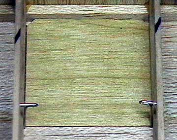
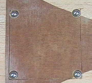
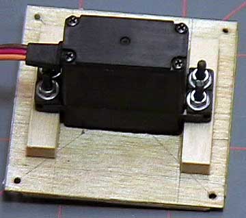
I decided I was going to use my preferred setup even though it made building the hatch covers much more difficult.  I 
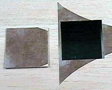
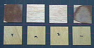
could have cut the plywood doublers before laminating them to the covers, but at that time I did not realize there was going to be a problem.  I ended up having to use a router after the fact.  If I had cut them out before hand it would have made the entire job easier.

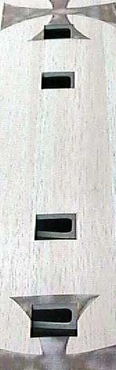
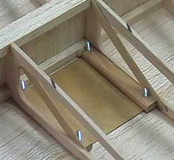
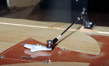
Although it is not clear in these images, I located the servos in bays that also have hinge support blocks.  This decision was made so that the control horns would be located close to a hinge which reduces slop in the control setup.


Make a template to locate the corners of the hatches.  Push pins through the sheeting. The first job is to cut the hatches from the wing skin.  The hatches are located partly in the inlays so it is not an option to cut the area out, discard it and cut hatches from plywood which is my usual method.

A template cut from plywood ensures the hatches are consistent in size.  I am avoiding making any type of pencil marks on the skins because the wing is receiving a natural finish and the skins are already sanded.

A pin is used to mark the four corners of each hatch.  The forward corners are the intersection of the spar and rib.  The rear corners are marked using the template.

The pin holes clearly mark the hatch outlines. The four pin holes that mark the corners of the hatch cover.  A flexible ruler makes it easier to cut in the chord-wise direction.
Carefully cut out the hatches with a sharp hobby knife. Use a very sharp knife to cut the hatches.  I strongly suggest that you do not attempt to use a saw on a moto-tool or similar method.  It is just too easy to have a miscut ruin the hatch cover or the skin.
All four hatch cut-outs. All the hatches have been cut out.  Up to now the job has gone fairly quicklyapproximately thirty minutes.
Glue hardwood rails to the ribs to mount the hatches. Normally I discard the wood cut from the skin and make a hatch cover from aircraft ply of the same thickness as the skin.  In this case the plywood doublers are laminated to the hatch covers which increases their thickness.  That means I can't simply lay the hatch mounts against the inner wing skin or the hatches will not sit flush with the skin.

Several fittings and adjustments get the mounts positioned so that they are in the same plane and the hatch flush with the skin.

If you look closely you can see a piece of plywood on the outboard side of the right-most rib.  It is simply a clamp block to prevent the clamps from crushing the soft balsa wood rib.

Normally I replace the hatch cut outs with plywood.  This design is unique in that it retains the cut-out portion so that a doubler is needed. The hatches shown with their respective doublers.  The hatches are not exactly the same size so each doubler is cut to fit its respective hatch coverhence the numbers.

The doublers are doing all the work and the hatch covers cut from the wing merely maintain the outward appearance of the wing skin.  Polyurethane glue is used to laminate covers and doublers using the method described here.

The outside of the hatch is counter-bored so the screw tightens against the doubler. Socket head #2 wood screws are used to mount the hatch.  The socket heads will help prevent a driver from slipping and punching a hole through the wing.

The hatch is counter-bored down to the plywood doubler.  I used a 1/4" brad-point drill bit.

The edges of all the hatches will be sanded slightly to allow for the finish.  They should be a slip fit and remove easily without prying.

Hatch mounts are reinforced with trusses.  The hatches are held in place with small wood or sheet metal screws. I tend to err on the side of caution.  I'm not sure that the mounts will be strong enough due to the amount of wood removed from the ribs.  The mounted hatch seems sturdy and stable, but I want to be sure the hatches will not be ripped from the wing due to flight loads.

Trusses are cut from 1/32" plywood.  Originally I cut them from 1/8" balsa but the mounting screws would have interfered with them.

Notice that the trusses are notched to fit over the ends of the hatch mounts.  The long edges of the trusses are sanded and rounded over to prevent them from sawing through the servo leads and extensions.

Servo mounts glued to doublers. The inside of the finished hatch cover showing the servo mounts.  The cutout area is routed, but it would have been simpler to cut out the plywood doubler before laminating the parts.

The servo mounts from the top of the lugs rather than from the bottom.  This means the eyelets have to be installed upside down (from the top of the servo).

The servo mounts could be smaller and I will probably saw them off about 1/8" from the holes for the servo mounting screws.

The thickness of the mounts is such that the top of the servo barely clears the inside of the hatch cover.  The servo arm needs to clear the hatch by at least enough so that the linkage does not rub the cover.

Outside of hatch showing hole for servo arm and holes for mounting screws. The outside of the finished hatch cover.  All screws are counter sunk so they tighten against the aircraft plywood doubler.
Inaccessible servos should use lock nuts for security. Normally I would use lock nuts here because these servos are not readily accessible for quick inspection.  I used normal hex nuts and a flat washer to test fit.  I would trust the hex nuts only if I used a thread locking compound to ensure they can not come loose.
A very neat servo installation that is easy to adjust and maintain. This method of mounting the servo allows use of the full servo travel.  It looks neat and has proven to be very reliable and easy to maintain.  Additionally, the geometry can be adjusted easily with the servo mounted in place.

A side mounted servo requires the linkage and hatch cover to be removed to adjust the servo arm.  Then it all has to be put back together again to check it.  Usually several fittings are necessary to get the correct geometry.  This gets to be very tedious — especially when trying to get two or more servos working in sync.

It would have been much easier to use the popular method of having the entire top of the servo visible.  I really do not like that way that looks so I made my life more difficult using this system.  There is enough clearance (barely) to put a clevis on the servo arm without it rubbing against the hatch cover.

The hardware to mount four servos and their respective hatches. If you ever wonder where weight comes from in a model aircraft, here is a good indication.  This is all the hardware used to mount the servos to the hatches and the hatches to the wing.
Not too shabby.
 
  The next step is to sheet the top of the wing.  Before I do that I will tape some strings inside the panel to pull the servo leads through.  The method of attaching the top sheeting is identical to that of the lower sheeting so that step will not be shown.  
 

Previous —
Next —

Sheeting a Model Airplane Wing
Building Ailerons and Flaps

Comments about this article


Back to Wing Construction Example
Airfield Models Home


Copyright © 2003 Paul K. Johnson