Airfield Models - Gallery

SR Batteries Fokker Eindecker E1

December 18, 2021


Home
About
What's New
History
Models Gallery
Model Building Safety
Articles
Mail & FAQ
Site Map
Site Feedback
Contact
Add to Favorites
Comments
Search Airfield Models

Back to Gallery


Airfield Models (http://www.airfieldmodels.com/)Detailing the SR Batteries 1/4 Scale Fokker Eindecker E1

This model is unfinished.  It is done to fly and could be done forever but there are a few more things I want to do.

  • Black gusset plates (I don't know what they're really called) on the outside of the rear fuselage.  I could not find a clear enough photo to show me what they look like so I've left them off for now.  I will probably print them on cardstock, cut them out, bend them, touch up the edges with a marker and then clear coat them after they are glued in place.

  • Redo the steps for the pilot to enter the aircraft.  They're too small in cross-section and basically invisible.  There are a lot of ways it can be done easily.

  • Fix the blemish on the pilot's left cheek.  I'm not sure how to do it, but I have a painter friend who can tell me if I should attempt it and how or if it's better left alone and we call it a scar from close shot by an enemy aircraft.

Update 08/04/2007.  None of the above items have been addressed and probably never will be.  The plane is done.

I will post updated photos if more work is completed.


Aces of Iron Pilot

Aces of Iron German WWI PilotThe pilot is made by Aces of Iron specifically for this kit.  The sculpting is superb.  The pilot looks very realistic although he's a little too old.  That doesn't bother me because I don't like seeing kids in fighter planes.

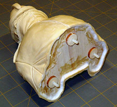
I began by cutting a base from scrap lite-ply to glue inside the pilot.  I spot glued it with medium CA and then made a fillet from micro-balloons mixed with epoxy.

To give the mounting bolts more to bite into, I glued three punch-outs from the lite-ply ribs to the bottom of the base.  The holes were drilled and tapped for 6-32 nylon bolt studs (bolt head cut off).  I didn't glue the studs in the pilot because I clamped alligator clips to them so the pilot could be manipulated while painting.

When the pilot was complete, the studs were discarded and replaced with new ones which were glued in place with thin CA.  In retrospect, I probably should have glued the studs in place with silicone so they could be removed more easily if necessary.

I began painting by airbrushing a faded black enamel overall except the face.  The face began with a base coat of flesh colored enamel.

The uniform had several washes applied of various colors mostly gray, black and burnt sienna.  After the washes were thoroughly dry I dry-brushed using medium gray.  The buttons and accouterments were painted using various grays followed by black washes and lighter gray dry-brushing.

The face was painted using the technique recommended by the Aces of Iron website.  I didn't like how theirs turned out because I thought it was too ruddy, but the basic idea applies.  I just removed more red before continuing by dry-brushing downward to leave red in shadow areas.  I also added some washes to darken creases around the eyes and shadows around the edges of the pilot's face and neck.

About a year and a half after completing this model Mike brought me the pilot whose head was almost completely detached.  The back of the neck was the only part still holding it together.  I used a small amount of thin cyanoacrylate to glue the head back together.  I then cut a hole in the base and reinforced the area with epoxy and chopped fiberglass.

Also see


Williams Brothers 1/4 scale Spandau machine gun

Williams Brothers 1/4 Scale Spandau Machine GunNeither the Spandau machine gun kit nor the Eindecker kit come with instructions for mounting the gun.  It's the wrong gun, by the way.  I don't know if anyone makes the right gun, but this one came in the accessory pack so it's what I used.

Edit 08/04/2007:  Maybe it is the right gun.

All the reference photos I have seen show the gun mounted off-center to the right as viewed from the cockpit.  I chose to take the easy way out and mount it centered so I could use the longeron in the hatch rather than spending another 20 hours creating a gun mount that probably would have still been wrong for a gun that's wrong.

All in all I like the gun.  Painting it was fun and the plane would look really bad without it.  Leave off the flash suppressor so that only the barrel is visible in front of the cooling jacket.

Don Carroll (aka "AbuFletcher" at RC Universe) informed me that I mounted the gun way too high.  In looking at it again, he was obviously right, so I relieved the top deck down to the longeron which lowered the gun by 1/8".

That still wasn't enough so I cut approximately 5/16" from the bottom of the gun.  Unfortunately, that exposed glued areas of the nylon bolt that would interfere with a nut.  I glued the gun in place using a thin bead of black silicone adhesive.  It is very secure but can be removed without damage if necessary.  An X-Acto blade can be slipped in between the gun and the hatch from underneath.


Steps

I bent a couple steps from music wire and drilled holes in the fuselage to mount them.  The actual steps have a larger, more rectangular cross section.  I would make them differently next time because the ones I made are all but invisible.


Bungees

Mike related to me that he has heard stories about the landing gear flexing enough to contact the forward flying wire which then wraps around the wheel and tears the wing apart.  I had not heard this story, but we could push down on a wing hard enough to cause the wheel to contact the wire.

I unwrapped the bungee and re-wrapped it tighter to help prevent any problems.  We lost some shock-absorbing capability, but it still has enough and I've never seen Mike splatter a model.


Rigging

When the building was done it was time to set up the rigging.  Mike and I set up the model on a large table and started making flying and landing wires.  We made them adjustable so we can account for any stretching that the wire does over time.

It took us several hours over two days before we were finally satisfied with the setup.  At this point everything was done and all we needed to do is check the engine, range check and fly.


Wind screen

The wind screen was added after the airframe was covered and finished.

A groove was carved in the upper deck to receive the windscreen.  I had planned to fill the groove with epoxy, insert the windscreen and then clean up excess ooze.  Then I had a brain storm.  The problem with clear epoxy is it would show the wood grain through the wind screen when viewed from certain angles.

I decided to use JB Weld instead.  It's not a perfect color match but much better than any other adhesive I have.  JB Weld is a metal-filled epoxy.

The excess ooze cleaned up easily with alcohol on Q-Tips which also created a nice fillet around the wind screen base.  Any event that would cause this windscreen to come loose would pretty much destroy the rest of the airplane!


Previous —
Next —

Finishing the SR Batteries Fokker Eindecker E1
Flying and Maintaining the Eindecker

Comments about this article


Back to SR Batteries 1/4 Scale Fokker Eindecker E1
Airfield Models Home


Copyright © 2005 Paul K. Johnson