![]()
|
|
|
|
|
|
|
|
|
|
|
|
|
|
|
|
|
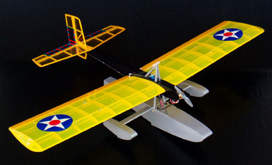
About the Splash-EThe BMJR Models Splash-E is a small flying boat designed for a geared MGK motor. The model was designed by Harry Stewart and featured as a construction article in Fly RC Magazine. The model is currently being kitted by BMJR Models and contains laser cut parts, CAD drawn plans a photo illustrated instruction manual and a complete hardware package. This model was in my shop for far too long for several reasons. First, as you may have heard, Florida had a few hurricanes this season. Two of them came through my front yard, but were downgraded to tropical storms by then. However, my electricity didn't notice the difference between the two when it went out and stayed out for quite some time. In the mean time I had a shoulder surgery that laid me up for a while. Lastly, getting a propulsion package assembled together that would actually work kept me stuck for a couple weeks while items were being shipped back and forth. More griping about this to come.
|
|
|
Impressive!If you've done much reading on this web site you'll see that it is not often that I sing the praises of any product. I am incredibly picky — especially in regard to kits and tools. The first thing I do when I open a new kit is pull everything out and look it over. What I'm looking at is overall quality and completeness. The next thing I do is look over the plans and instructions. I usually do this while I'm still in the middle of another project. The reason is that there are often things that I will modify due to personal preference or because the design is lacking somehow. Sometimes there are challenging aspects to the kit as well. I can mull these things over by studying the project in advance. More often than not I have a game plan before I'm ready to begin building the model. Lastly, there may be equipment that I'll want to have on hand when I start the project. The pre-screening allows me to get things on order so I'm not waiting. There was a point to all of that, but now I forget what it was. Anyway... A couple things about this kit caught my eye immediately. The kit arrived in two very sturdy mailing boxes which are also the kit boxes. All the parts were well packed in heavy poly bags. Nothing was damaged. The kit actually comes in one box but the manufacturer had found an error and sent replacement parts. The error was that a couple of the laser-cut sheets were the wrong thickness wood. What really impressed me about this was that the manufacturer caught the error and took the initiative to send out the correct parts. Service like this doesn't happen often these days and I take note when I receive it. The quality of the kit is excellent. All of the wood is very good. There were a couple of parts that I replaced due to personal preference. The strip ailerons were both good quality, but the weight differed by enough that ballast would have been required in the wing having the lighter aileron to make the aircraft balance laterally. There is also a lot of basswood in the kit. Flying weight of the finished aircraft is supposed to be 13 to 15 ounces. I had my doubts about that simply due to all the components. For example, the spreader between the sponsons is a piece of basswood that measures 1/8" x 1" x 15-1/2". I felt this piece was heavier and stronger than really necessary so I replaced it with the heavier balsa aileron which was much lighter and has a more attractive airfoil shape. In addition to the kit I had the original construction article as a reference which was helpful. The article indicates that the ailerons on the prototype were built up using ribs and 1/32" balsa skins. I chose to do the same. The built-up ailerons are about 2/3 the weight that a pair of the lighter of the supplied ailerons would have weighed and are significantly lighter than a pair of the heavier aileron would have been. I also replaced two of the 3" x 1/16" balsa used to sheet the hull, floats and fuselage because they contained several small worm holes. I could have simply filled the holes, but I chose to replace the wood with 4" x 1/16" which meant fewer joins and not worrying about sealing the holes. I do not consider the wood to be defective because worm holes are normal in balsa and nothing to be concerned about. I added the supplied balsa to my stock for use on other projects.
I did not replace any of the supplied hardware. I also didn't need to buy any hardware for the model — the pack was actually complete. This model has functional flying wires and landing wires. The wings slide onto short carbon fiber rods that are glued into the fuselage. Spider wire fishing line is supplied to rig the wires. The wires are attached to the wings with what I think is another very nice touch — brass wood screws. I would bet that 90% of all manufacturers would supply cheap steel screws that will rust. The flying wires from each wing are joined together using control line connectors and rubber bands. I don't think I would perform outside maneuvers with this plane because I don't trust the setup that much. I added a safety wire to join the landing wires but it has enough slack to allow the model to be disassembled without cutting the wire. A better setup would be to semi-permanently wire the two sets of flying wires together and keep the model assembled. The wire would need to be cut to remove the wings. Note that all radio gear is accessible with the wings attached.
|
|
|
Construction
The plans are clear and very easy to follow. The instructions are illustrated with color photos and provide a logical building sequence which I chose not to follow for reasons I can't remember now. I built the entire model using Ambroid wood cement and Weldbond adhesive. Ambroid was used on all joints exposed to the outside because it sands at the same rate as balsa and is waterproof. Weldbond was used for formers and ribs because it is incredibly strong. All of the parts that are meant to be in the water were sealed with several coats of dope. A water-proof adhesive wasn't really necessary but it's still a good idea. I began construction by joining the multi-part fuselage and hull sides so they would be ready when I got to them. The parts key together and assembly is pretty much fool-proof. Even so, I built each pair of sides directly on top of each other to ensure they were identical. After the sides were dry, I added the various doublers to the insides. The doublers play a major role in aligning the trapeze assembly so I took great care with this step.
Next I assembled a jig using magnets to build the struts to ensure they were absolutely identical. This is important because even a small amount of misalignment here will prevent the fuselage from aligning with the hull. Keeping this thought in mind, I assembled another jig that allowed me to glue each strut to its respective fuselage side while one side was on top of the other. This ensured both sides and strut assemblies were identical. Take a look at the photo gallery to save me 1,000 typed words. The one design flaw is the lack of vertical support in the hull. I strongly suggest that you add a few 1/8" square balsa vertical supports in unsupported areas between the formers to prevent the finish from collapsing the hull. More about this later. The instructions indicate that the hatch in the forward hull can be located as shown on the plan or moved forward if necessary depending on where the battery will best balance the model. Unfortunately, the design makes it next to impossible to completely assemble to determine the balance.
I decided to make my life easy by replacing the stock former with one cut from plywood. The new former has a cut-out large enough to pass the battery. That allowed me to build the hatch and still be able to place the battery in either compartment for balance. The servo mounting system is frustrating. The aileron servo mounts to the top of the fuselage and is accessible. The elevator and rudder servos are mounted below the fuselage inside the trapeze assembly. It is next to impossible to get to the mounting screws due to the width of the hull. I ended up using socket head wood screws to mount the servos so that I could use a ball driver, but it's still a chore.
I made a couple additional housings for additional support, but I don't know how well it will hold up. If the tubes come loose in flight the pushrods will probably collapse followed by the plane diving into the ground. Overall I think the control system could stand some more development. The wings are simple and straight forward. Again, all the parts fit well and each wing panel required less than an hour to build. In fact, it took me longer to sand them than to build them. One item that threw me off is that it looks like the shear webs at the wing root are upside down and will cause the wing to have anhedral. I kept looking at the parts wondering why they were drawn on the plan upside down. Then I realized that the fuselage tapers from bottom to top so that the angle of the shear webs would provide the correct dihedral angle when subtracted from the angle of the fuselage sides. To clarify, even though it looks wrong, the top of the root ribs cant outward, not inward. One feature that I like is that the basswood anchor blocks for the flying wires go all the way from top to bottom of the wing. I've seen some designs having functional flying wires where there were separate mounts on the top and bottom of the wing. That setup is asking for the wing to be ripped apart. The single anchor block allows the load to be transferred through the wing making a much stronger and more reliable setup.
|
|
|
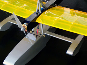
Buying a Power SystemThis was the most aggravating part of the build and while I gripe, please keep in mind none of this is the fault of the design or the kit. My buddy Mike has much more experience with electrics than I do. I showed him the kit and he felt the recommended power was inadequate to the point that the model may not even be able to get off the water. The last thing I want to do is build a model that doesn't fly. I contacted the manufacturer who confirmed that the recommended MGK motor is marginal power for this aircraft. It will fly the model, but don't expect much more than that. I have no idea what an MGK motor is, so I was taking other people's word for it who know a lot more about it than I do. The MGK motor mounts on a horizontal tray using a retainer made from an included paper clip and rubber band. Because I was using a firewall mounted motor, I replaced the balsa firewall with one cut from 1/8" aircraft plywood.
The gear box turned out to be too large for the fuselage, so I sent it all back and ordered an AXI 2208/20 out-runner motor from Hobby Lobby and a 3-Cell pack from RC Toys (Tanic Packs). The motor could not be mounted as is and required the hardware and prop adapter to mount the motor backwards directly to the firewall. Mike described the type setup that was necessary. I called Hobby Lobby and explained to them what I needed but didn't know what the actual parts looked like or the part numbers. In speaking with three different salespeople people it became clear that none of them seemed to understand what I was trying to get across. Apparently I wasn't explaining it very well, but I really don't understand electrics so I was depending on them to fill in the blanks. Eventually one of the salespeople gave me a link to the part he thought I needed and it looked like it would do the job. So I OK'd it. What I actually received was a different part altogether. When I called Hobby Lobby I was told that I received the part I asked for. At this point I was stuck and extremely aggravated because the rest of the model was finished including paint. The fuselage was still laying in pieces on my bench because I couldn't build a firewall until I could mount the motor. To mount the motor, all I needed to do was bolt through the firewall from the back directly into the motor. This requires a special prop adapter. The set that includes the adapter also comes with a motor mount that isn't necessary which raises the cost significantly. Including multiple shipping back and forth, I ended up paying nearly $50.00 for a $6.00 part. This is just one thing about electrics that is extremely annoying. There are apparently no standards whatsoever when it comes to mounting the things and with every new type of motor comes a new mounting system. Some of the systems are ridiculous such as a single set screw holding a powerful electric motor to its mount. I wonder what genius came up with that one and why it made it to the market.
|
|
|
FinishingThe instructions state the following for finishing the hull: "Brush on a couple of heavy coats of Sig Nitrate dope, sand lightly, then brush on a couple of heavy coats of Sig Sanding Sealer and sand again until smooth. Apply your favorite colors with a spray can from the hardware or automotive store. Finish up with a couple of coats of clear acrylic spray on the hull and floats." Before enclosing the hull with the top sheet, I brushed on 3 or 4 coats of clear nitrate dope to the inside of the hull to waterproof it. I coated the inside of the sheeting with laminating epoxy to ensure it was waterproof and then taped the sheeting in place allowing the epoxy to double as the adhesive. At this point I block sanded the outside of the hull until it was perfectly flat on all sides. It was then finish sanded using fine paper. I brushed on a couple coats of clear nitrate dope to the outside of the hull to seal the grain. I then sprayed several coats of sanding sealer and sanded between coats. I noticed the sides of the hull were beginning to bow in between the formers. I thought that I had missed an area when sanding and filled the low areas using HobbyPoxy Stuff. A couple more coats of clear dope were sprayed on which worsened the bowing of the hull sides. I came to realize that the dope was shrinking and collapsing the sides of the hull. In fairness, it has been a long time since I have applied a dope finish and I have never applied an all-dope finish without covering to a sheeted surface before. Had I used a low shrink dope the problem would have been lessened considerably or perhaps not occurred at all. I finally gave up trying to fill the grain or fixing the collapsed areas. The added weight would not have been acceptable. I did tissue the bottom of the hull to add a little durability. I'll take the hit for this one because I feel like I basically botched it. Considering my experience as a model-builder I should have added more vertical support inside the hull in the first place. The sides are thin, lightweight balsa wood which is fine from a structural standpoint. They are strong enough to do their job. Also, I used far more coats of dope than called for in the instructions. Had I used the few coats recommended and then switched to paint, the hull may not have collapsed so much. For example, Rustoleum paint doesn't have near the shrinkage that dope has. Learning from my experience with the hull, I tissued the fuselage which resulted in many fewer coats of dope needed to achieve a much better finish. Therefore, my recommendation is to add the 1/8" square balsa vertical supports between the formers as previously mentioned and to tissue the entire structure. The rest of the model was covered with Oracover Lite film available from Hobby Lobby. Even though I really like this covering for its low weight, ease of application and ability to go around compound curves, I strongly suggest that you avoid the transparent yellow. I have ordered two rolls of it at two different times and both of them were bad. The first roll had ripples in the pigment/adhesive that are clearly visible. The second roll was mottled. Both rolls appear to be closer to orange than yellow. I was attempting to replicate a golden era Army Air Corps finish, so I cut stripes of red and blue and drew alignment guides on my glass workbench. After aligning each piece with a 1/16" overlap I ironed the stripes together. I then brushed acetone along the edge of the seam and allowed it to dry. The completed pieces were ironed to the rudder and elevator. The remainder of those two components were covered with yellow as were the fin, horizontal stabilizer and wing. Unfortunately, the trailing edge of the wing is really flimsy being only 1/8" wide and having ribs spaced a fair distance apart. The trailing edge collapsed when I shrunk the covering. I ended up stripping off the covering and replacing the trailing edge with harder and wider stock. The wing was recovered with transparent Monokote because I didn't have any more Oracover.
|
|
|
ConclusionWhen I first saw photos of this model I thought it was one of the ugliest model airplanes I've ever seen. I think the manufacturer would do well to take new photos of the model that are more complimentary because it's really a cute little airplane. From reading this article it may appear that the model presents a lot of problems. I won't say this was a real fun project because there were a lot of frustrations along the way. However, most of the problems I encountered were either my fault or my lack of experience with electric propulsions system. This is one model where I'd like to have a do-over. It should have been a fun build and should have gone much faster and much more smoothly. I do recommend this model while also recommending that you modify a few things. Add the vertical supports in the hull and mount the elevator and the rudder servos in the fuselage behind the wing. I haven't measure it out, but I suspect the servos can be mounted on the sides of the fuselage with one above the other so that they clear each other inside the fuselage. I would also change the pushrod system to a pull system using lightweight, stranded fishing line, such as Power Pro. Both of those modifications are simple to make and should actually make the build easier. With all that being said, I believe the Splash-E represents the best in kitting. The quality and completeness of the included components is excellent as are the plans and instruction manual. I recommend the model for experienced builders due to the lightweight and delicate nature of the model. The wings are such that its best to have another person hold them while the covering is shrunk so that they don't warp. While the model is not difficult to assemble, building the trapeze and setting up the functional flying wires add a degree of difficulty which require experience and care to accomplish successfully. The kit builds into an attractive airplane that can be left assembled for display which is always a plus. I'm looking forward to building more kits from BMJR. I've looked at their other offerings and am tempted to build several of them. Their line includes several nice looking, lightweight models such as the Miles Magister designed by Dave Platt.
|
|
|
|
|
|
|
|
|
Copyright © 2004 Paul K. Johnson
|
|


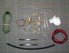 One other thing about this kit that really impresses me is the
hardware pack.
More often than not kits have incomplete hardware packs that contain cheap
hardware. I have always been very picky about the hardware I use in the models I build
and regard reliability and quality above all else.
One other thing about this kit that really impresses me is the
hardware pack.
More often than not kits have incomplete hardware packs that contain cheap
hardware. I have always been very picky about the hardware I use in the models I build
and regard reliability and quality above all else.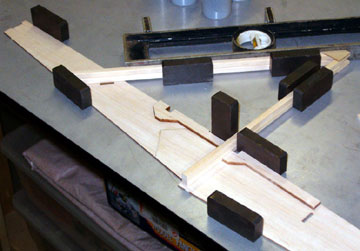 There is nothing particularly difficult about building this model
but some areas require a bit of experience to ensure accuracy.
There is nothing particularly difficult about building this model
but some areas require a bit of experience to ensure accuracy.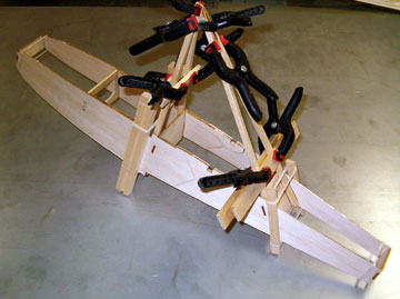 While the sides were drying I built the
outrigger floats (this model has four fuselages) which took
maybe an hour. These were put aside because they won't be needed again
until much later in construction.
While the sides were drying I built the
outrigger floats (this model has four fuselages) which took
maybe an hour. These were put aside because they won't be needed again
until much later in construction.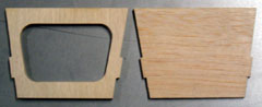 For example, the
servo mounts can not be glued in place until the fuselage is
glued on permanently. By that time, the hull and fuselage should already
be painted.
For example, the
servo mounts can not be glued in place until the fuselage is
glued on permanently. By that time, the hull and fuselage should already
be painted.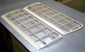 There is plenty of room in the fuselage behind the wing to mount the servos
which would be a better place to mount them. The
There is plenty of room in the fuselage behind the wing to mount the servos
which would be a better place to mount them. The
 Mike recommended a
Speed 300 size motor for the model. I placed an
order with
Mike recommended a
Speed 300 size motor for the model. I placed an
order with