Airfield Models - How To

How I Make Magnetic Fixture System II Vertical Presses

April 02, 2024


Home
About
What's New
History
Models Gallery
Model Building Safety
Articles
Mail & FAQ
Site Map
Site Feedback
Contact
Add to Favorites
Comments
Search Airfield Models

Back to Magnetic Building System


Airfield Models (http://www.airfieldmodels.com/)How I Make Vertical Presses

News About My Magnetic Fixture System (Pricing and Availability)

I really like the way these pieces look when they're finished and have often contemplated making the entire system from hardwood.  There are a few reasons I haven't but I'm still considering it and haven't ruled it out.  It's mostly a matter of finding space for the tools I'll need to acquire and the fact that the price of my system will increase substantially.

Of course there's nothing saying that I couldn't have a hardwood line for those who want it and continue producing the birch plywood line for builders who don't care about what wood is used and would rather pay less for a tool that works just as well.

Even though the Vertical Presses are simple the process of making them is somewhat involved.  I have a quality set of digital calipers on hand throughout the process.

I commissioned Joe Tabajdi to make two drill jigs for me.  One of them has a removable drill guide that is replaced with a tap guide for the Press Bolt.  Joe also made the drill guide I use to drill the mounting holes in the fixtures.

I keep telling him he needs a web site of his own because he does excellent work and nobody can hire him if they can't find him.


Getting Started

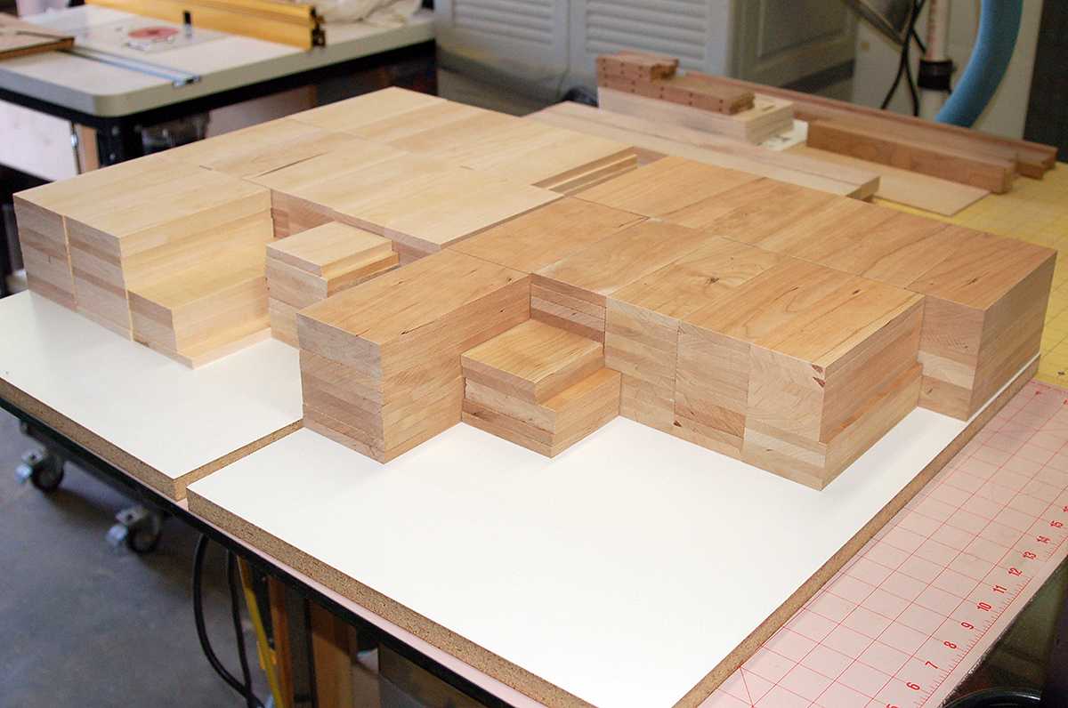
I begin with boards from the sawyer that are generally 4" to 12" wide and up to 6' long.  I ask them to be planed to 7/16" thick so I can do the final thicknessing because I've found that tolerances from wood mills are all over the place.  The thickness I actually need is 3/8" but if I ask for that then I'll get wood from 5/16" to 1/2" thick.  Anything too thin obviously can't be used to make these.

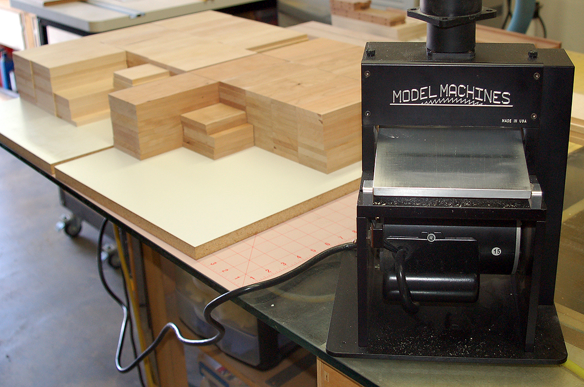
Eventually I'll have no choice but to invest in some real tools - a jointer, planer and thickness sander.  I have the tools I need for the volumes I'm working with now.

I cut the boards to length and width.  Each width is calculated taking into account saw kerf.  The length is twice the length of a Vertical Press plus kerf and waste.

Shown here are maple (left) and cherry (right) boards that will make approximately eight hundred vertical presses of each.

I know of only two miniature thickness sanders.  One is made by Microlux and this one by Jim Byrnes.  The Microlux sander uses drums and is sold in the USA through MicroMark.  Although I've never used it I would never buy it because it uses dedicated sanding drums that are not a commonly found item.  The drums are specific to the machine.

The Byrnes sander uses a half-sheet of sandpaper and the only limitation is the thickness of paper used.  The paper is held in place by aluminum wedges.  If the paper is too thick then the wedges won't seat deeply enough.  I found out when I couldn't use cloth-backed 60 grit paper because I needed to remove a lot of thickness from some boards.  I really needed a thickness planer for that or to learn to use a hand-plane.

I've used paper as coarse as 120 with no problem.

This sander is incredibly well-made and very robust.  I can consistently achieve tolerances within 0.002".  The trick to using this machine is knowing when to switch to finer grits of sandpaper.

Unlike full-size thickness sanders, this machine doesn't self-feed so you have to use push-sticks to feed the stock through.

Dust collection works very well.  I used one of the junk transmitter straps that came with a radio to support the Shop-Vac hose.
I built this sled specifically to hold Vertical Press stock to feed through my router table.  The base is two laminations of 1/4" birch plywood.  At some point after making the Vertical Presses shown in this article the base bowed really badly so I need to make another one.

I bought a piece of 1/2" aluminum plate for the next version.  Warping won't be a problem.

The arrow points to the guide bar that spaces the sled from the fence while keeping the stock parallel to it. The distance to the cutter is controlled by the fence.

The fence is made by Incra and is adjustable in 0.001" increments.

   The thumbscrews on the right hold a sacrificial piece that prevents tear-out of the stock as it exits the cutter.  The hold-down clamps could be better.  A plate that provides uniform clamping over the stock would be a huge improvement.
The arrow points to the sacrificial piece.
All cuts are made in multiple passes.  The first cut hogs out most of the wood.  I leave about 1/64" to remove in depth and thickness.  The cutter is replaced with a new one and a final cut is made.
After the tails are cut on all the pieces the stock is cross-cut in half.

Sometimes there's still some clean-up to do.

   A few seconds with a sanding block takes care of it.
Ready for the next step.
The front-edge is cut with a bull-nose bit.  This cut is also done in multiple passes.
There's not a lot of room for error when using a bull-nose bit.  If the wood is the exact thickness of the bit then the bit has to be dead-on.  Otherwise you'll have a groove cut into the wood that is easily seen.

The micro-adjust dial for the Incra fence is an awesome feature.  It makes it very easy to get whatever degree of accuracy you need.

   All the routing is done.  The routing alone usually takes a couple of days.
You can see that groove I was talking about on the right side of this piece.  That can happen for several reasons: the board was cupped, it wasn't held down properly on the sled, there were wood chips under it, something got under the sled, the bit was the wrong height, the router table is bowed, etc.

To get perfect results everything in the system has to be perfect.

Everything in my system isn't perfect so I end up having to clean up some after all the routing is done.  Fortunately it's only a handful.  Most of them come out with no clean-up required.
Now it's time to separate the blanks into individual Vertical Presses.  This is a Byrnes table saw which is another excellent tool and very highly recommended.  I purchased a larger table for it which increased the rip capacity to over 6" with the fence and micrometer attachment.

I have a very good collection of blades for this saw - most of them are carbide-tipped and all of them are too big.  They are either 4-3/8" or 4-1/2".  What that means is that when the blade is raised they cut into the bottom of the table.  That's not something I care about because I don't concern myself about resale value of my tools.  I don't buy them with the idea that I'm going to sell them one day.

   The tails are trimmed to length.  I could probably do this while the blanks are one piece but I feel better about cutting them individually.
Joe Tabajdi made this drill jig to drill the mounting holes.  It's why the Vertical Presses are a perfect fit on the Magnetic Fixtures.
Joe also made this drill jig for the press bolt.  The hardened drill guide is removable.
It can be replaced with a tap guide.
  A bevel is sanded on the both corners of the tails.
The sides are lightly sanded.  Any that have deep saw marks are discarded.
As a finishing touch all holes are hit with a conical sander in a moto tool.  They're now finished and ready to go.
The Clamp Pad is the simplest part to make in the entire system but I consider it essential.  It prevents the press bolt from damaging the work being clamped.  The hole in the pad is large enough to allow a slight angle from 90° between the press bolt and the clamp pad.
 
  Obviously a fair of work goes into these.  I reject a lot of them for various reasons.  I'm particular about pieces I would put in my personal set and that's my standard for what goes into stock and what gets rejected.  If I'm looking at a piece and there's something bugging me about it and can't tell immediately if it's bad enough to reject I just ask myself if I would keep it for myself.  If not I toss it.  
 

Previous —
Next —

How I Make Magnetic Fixture System II Magnetic Fixtures
Magnetic Fixture System II

Comments about this article


Back to Magnetic Fixture System II
Airfield Models Home


Copyright © 2021 Paul K. Johnson