|
|
|
|
How
to Install a Fuel Tank in a Model Aircraft
Installing a
fuel tank in a model airplane is a fairly simple process.
It's even easier if you aren't trying to stuff in a tank that barely fits the tank
compartment. Having some space around the tank will allow the tank be
positioned with the least amount of strain on the
fuel lines as well as making insertion less frustrating and tedious.
Whenever you are working with a fuel tank, keep the work area as sterile as
possible. The previous article describes how to clean and assemble the
tank. If you have not washed the tank out, then now is a good time to
disassemble it and clean out the tank and the lines.
Tips
- Ensure that the
engine mount
bolts do not extend beyond the blind nuts into the tank compartment so that they can not puncture the fuel
tank.
- If you are installing the tank in a balsa-dust filled structure, then
chances are some of that dust will make it into the fuel lines. Before
you begin, vacuum the inside of the model or blow the dust out using
compressed air.
|
|
|
|
Background
My Stik 30
was originally built around my O.S. .30 Wankel engine. I took the
engine out after the first day of test flights due to its very high fuel
consumption. It was replaced with a Webra Speed .32 2-stroke
engine.
Exactly a week after completing the model, I rolled a
wing
tip into the ground during a touch-and-go which resulted in a totaled
fuselage.
The new fuselage was not to set up for the Wankel. The Webra had
unresolved idle and transition problems so it
was replaced with an O.S. .46.
The plane was already nose-heavy with the Wankel and the Webra. The .46
made the problem even worse. By the time the
Center of Gravity was where I like it, My Stik 30 flew like a dog due to
massive amounts of lead in the tail.
The only way to save this plane was a major weight-reduction surgery
— nearly
10 ounces of weight was removed from a plane having a
wing
area of approximately 450 in2.
The modification involved installing the Wankel which required the
firewall
and fuel tank to be modified. This article details the tank
installation.
The only reason I bring all this up is so you understand why this firewall
looks like Swiss cheese.
|
|
|
|
Installing the Fuel Tank
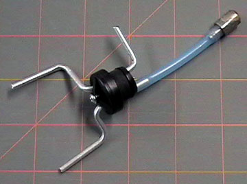 |
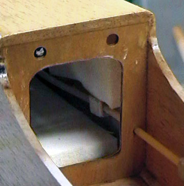
Because of the shape of the Wankel and the way it mounts,
the fuel lines have to come through the firewall around the outside of the
mount — not through the center. Creative tubing
bends were necessary as well as new holes in the firewall for the fuel
lines to pass through.
I used aluminum tubes on this tank because they bend more easily
than brass.
As shown here, the metal tubes are too long and must be trimmed to about 1/2".
Always deburr metal tubing to prevent it from cutting fuel lines
|
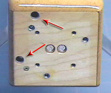 |
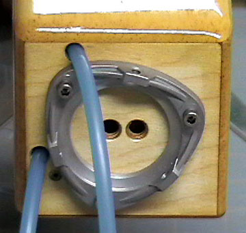
The arrows point to the new holes for the fuel lines.
The four holes arranged in a square pattern are the engine mounting
holes for the O.S. .46 that was replaced by the Wankel.
The three larger holes are the holes for mounting the Wankel.
All the unused holes were filled with
silicone sealant to prevent
fuel and oil from entering the airframe. |
 |
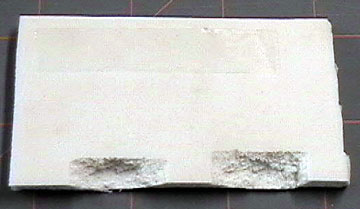
It is a good idea to line the tank compartment with
foam rubber to insulate it from engine vibration and to prevent the tank
from moving. Tank movement can cause the fuel lines
to kink which
will cause many headaches at the field.
This is a good place to use older foam that's kind of ratty looking,
but is still spongy.
|
 |
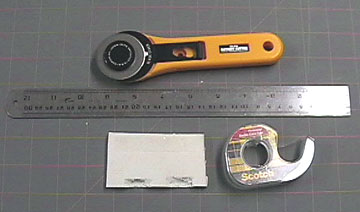
Trying to keep the foam in place while the tank is slid
into the compartment can be a lesson in frustration. Use
double-sided tape or
spray
adhesive to hold the foam in place so you can
concentrate on inserting the tank and not fiddle around with
uncooperative foam that won't stay where you want it.
In this case I tried double-stick tape, but it wouldn't stick inside
the tank compartment. I ended up using spray glue instead. |
 |
Here you can see the foam inserted in the tank
compartment. There is a piece above the tank as well. |
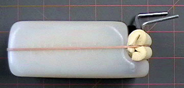 |
A piece of latex foam rubber is rolled up and rubber banded to
the front of the tank
has a couple useful purposes: It prevents the tank from directly
contacting the firewall which can help prevent it from being punctured
by the engine mounting bolts as well as reduce vibration transmitted to
the tank.
The foam will also help prevent the delicate tubing from being bent
or damaged. |
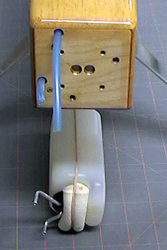 |
Many people believe that a tank is not sealed if the
metal tubing can rotate in the stopper. That is not true.
The stopper should be snug, but it does not need the life squeezed out
of it. A properly sealed tank will allow the tubing to rotate.
Nevertheless, a tank should always be tested for leaks before installation.
It should also be checked to ensure there is no blockage in the system
by blowing through one of the tubes.
In this case, the ability of the tubing to rotate is very helpful.
I arranged the tubes so they more or less
line up with the holes in the firewall. The tubes were not aligned
properly when this photo was taken, however. |
 |
Fuel lines are fed through the firewall and into the
radio compartment. They will be used to pull the tank in place.
Use one hand to guide the tank while using the fuel lines to pull the
tank into place. Every inch or so, pull on each fuel line
individually to ensure that the lines are not kinking inside the tank
compartment.
If you look carefully, you can see that the aluminum tube has been
trimmed to its final length. |
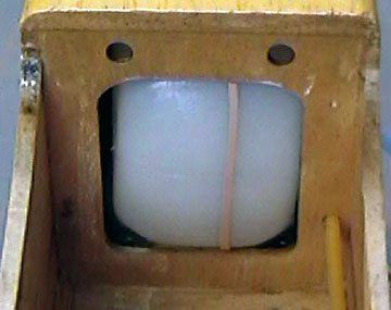 |
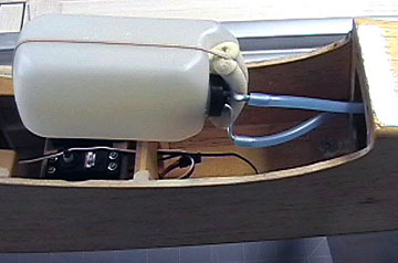
The tank in its final position. This rubber band
will break soon. That's ok because now that the tank is in place,
the foam it was holding will remain in position without the help of the
rubber band. |
 |
The fuel lines are located outside of the Wankel engine
mount. In the next photo you can see why they could not come
through the center of the mount. |
|
|
|
|
Testing the Installation
Before you go to all the trouble of installing the engine,
throttle linkage,
etc., check to ensure that flow through the fuel lines is not obstructed.
With neither line
connected to the engine, blow through a line. There will be a little
resistance, but not too much. If you can't blow through the tube,
then something is blocked.
You may need to pull the tank back and then tug on the fuel line to remove a
kink. If that doesn't work, then you may need to remove the tank
completely and find out what happened.
If you can't blow through the tank, then the engine will not be able to draw
fuel. It is not a problem that will go away by itself so you may as
well fix it now. Otherwise you will be at the field tinkering with the
installation instead of flying.
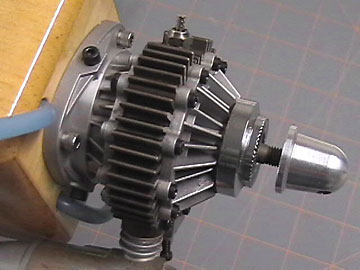 |
As you can see, there is no space between Wankel and its
mount for the fuel lines to come through. Fortunately, 2
and 4-Stroke engines usually have enough room between the engine and their mounts
to pull the lines through which simplifies installation. |
|
|
|
|
|
|
|
|
Back to Model Aircraft Engines
Airfield Models Home |
|
|
|
Copyright © 2004 Paul K.
Johnson |
|
|

