Airfield Models - How To

Make a Wire-Splicing Jig

December 19, 2021


Home
About
What's New
History
Models Gallery
Model Building Safety
Articles
Mail & FAQ
Site Map
Site Feedback
Contact
Add to Favorites
Comments
Search Airfield Models

Back to How-To Articles


Airfield Models (http://www.airfieldmodels.com/)How to Make a Wire Splicing Jig

Modeler's often have to do various wiring chores particularly those who fly R/C models or use electric systems.  For years I've used a set of "Extra Hands" to hold wires while I spliced them together with solder but there are things I don't like about it.

Extra hands make aligning the wires more difficult than necessary.  Usually the setup is precarious at best.  Lots of tweaking is required to arrange the wires so they'll stay aligned until the soldering is completed.  Additionally, the alligator clips can damage insulation around the wire.  Extra hands are good for some soldering tasks.  I just don't like them for wire.

My friend Mike came by one day and said he had seen something that made the whole task easier.  He described it to me and within an hour I made Mark I for him.  I used silicone adhesive to glue the fuel tubing to the base, but it didn't hold up long.  Mike tells me it fell off within a week.

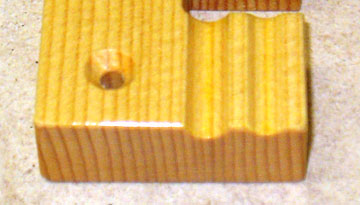
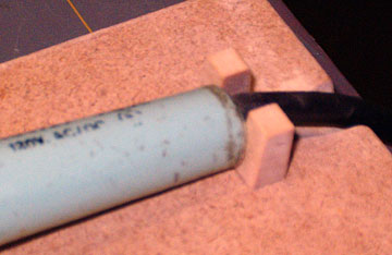
I made a second mark but it was too long.  I hadn't thought about that until it came time to use the jig.  Too much of the wire had to be separated to slide it into the tube.

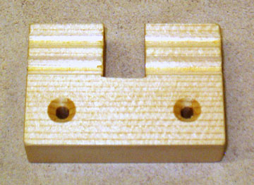
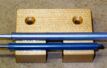
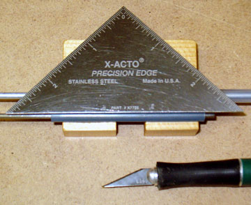
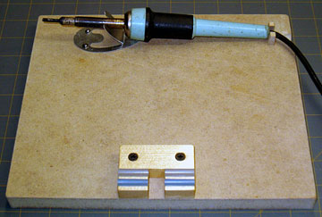
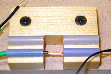
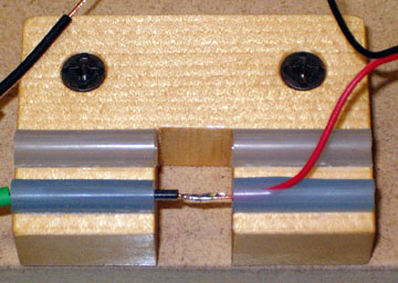
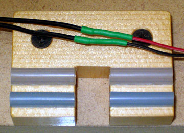
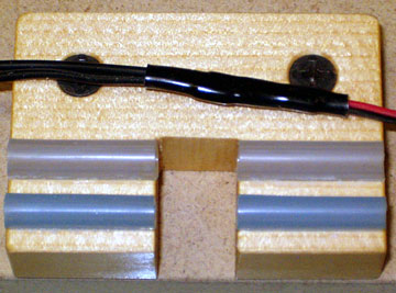
This is Mark III which has been going strong with no problems.


Making the Jig

The jig is made from a scrap of wood. I used a piece of 1/2" spruce that was lying around the shop eagerly waiting to turn into something useful.

The cutout is where the soldering iron is used.  Two channels were cut on my shaper table using a rounded veining bit.

You can carve out V's with a knife, use a file or whatever you've got to make the channels.

Cut grooves to glue fuel tubing into. Another view of the two channels.  One channel is for large fuel tubing which works well for electric motor wiring.

The other channel is for small fuel tubing which is good for servo leads.

Insert a rod into the fuel tubing to keep it straight while the glue dries. Put a straight metal rod or tube inside the fuel tube to keep it straight.  Clean the fuel tube with alcohol and then glue it in place using CA.
Use a knife with a straightedge to cut a slit in the top of the fuel tube. When the glue is dry, use a straightedge and a sharp knife cut a slot in the top of each tube while the rods are still inside the tubes.  Remove the rods.

Trim off the excess fuel tubing in the cutout and at the ends.

A soldering station that prevents the soldering iron from falling off. This is my soldering station.  I've wanted to make one for a long time and have finally gotten around to it.

The soldering iron is resting on an aluminum stand screwed to the base.  It came with my Coverite trim iron and was pretty much useless because the tool and the stand are both light.  The weight of the cord drags my trim tool off the table.  I'll probably use the soldering stand for the trim tool until I make a dedicated stand for my irons using the same basic idea.

You can bend a rest easily from coat hanger wire.  You may be able to attach the rest to the base with landing gear straps, but if the rest gets hot enough the straps may melt.

I suggest you make straps from an aluminum soda can or similar material.

A stop at the base of the soldering iron increases safety. This stop prevents the soldering iron from falling off the table into my lap when I bump the wire.  it was made from a scrap piece of hardwood.

Note the groove cut into the base of the station.  It allows the soldering iron to seat fully and won't chafe the cord as much as a sharp edge.

I plan to add some more jigs to the base.  For example, I will get some copper household wiring and attach alligator clips to it.  I'll drill a series of holes in the base for the wires to plug into.


Using the Jig

A "universal" female plug and a Futaba plug. The "universal" female plug at the bottom comes with the Sirius field charger.  Although the Sirius charger is excellent and I highly recommend it, I don't like the plug I'm always plugging things into it the wrong way.

All the RC equipment I use has the same type of plugs so I have no use for a universal plug.  I clipped it off and replaced it with the Futaba plug at the top of the photo.

I saved the original plug just in case I ever need it.  I can always solder a Futaba male plug on the other end and it will plug into the new plug.

Strip the wires and slide them into the jig. Aligning wires is easy with the jig.  You can either tin the wires in advance or not.  I don't find that pre-tinning the wires gains anything.

To the bottom left of this photo you can see heat shrink tubing.  Several times I have made the mistake of forgetting to put the heat shrink on before soldering and had to de-solder to correct it.  I've gotten a lot better about it.

Tom posted in the Guest Book (6/29/2006) that joining the wires as shown here does not create the strongest solder joint.

Tom suggests the Western Union Splice (scroll almost to the bottom of the page) which will obviously create a strong joint.  Note that no matter how you do it, you should not put a lot of strain on your servo wires particularly to the point where the strength of the solder joint becomes an issue.

Solder the wires together using rosin core solder.

The slit in the top of the tube allows the wire to be removed after being soldered into a single piece.  Just peel it out.

Heat shrink tubing protects the solder joints and prevents shorting of the wires. Don't forget the heat shrink.
A second piece of heat shrink keeps the wires together. I like to use a second piece of heat shrink to hold the wires together.


Previous —
Next —

How To Make a Split Fence for a Dremel Router/Shaper Table
How to Make Board-Edge Clamps

Comments about this article


Back to How-To's
Airfield Models Home


Copyright © 2005 Paul K. Johnson