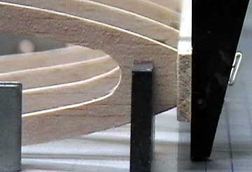
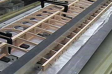
Airfield Models - Wing Construction Example

Add the Sub-Leading and Trailing Edges to a Model Airplane Wing

December 18, 2021


Home
About
What's New
History
Models Gallery
Model Building Safety
Articles
Mail & FAQ
Site Map
Site Feedback
Contact
Add to Favorites
Comments
Search Airfield Models

Back to Wing Construction Example


Airfield Models (http://www.airfieldmodels.com/)Add Sub-Leading and Trailing Edges to the Wing

This page will describe gluing the sub-leading edge and trailing edge in place.  When that is done I will leave the wing to dry over night.

To this point I have spent a little more than 30 minutes building this wing.  That includes setting up the board, dry-fitting the parts and gluing the ribs, webs and spars in place.  All of this was completed in one building session.  The steps on this page are more of that same building session.


Sub-Leading Edge

A Sub-Leading Edge is often used when a wing is fully sheeted or has leading edge sheeting (D-Tube wing).  It is glued on to the front of the ribs then sanded to fair into the ribs before the sheeting is glued on.

The purpose is to anchor the sheeting to something solid as well as help prevent the sheeting from sagging between ribs.  It also has the benefit of strengthening the leading edge.  Because the leading edge is laminated to the sub-leading edge and to the forward edge of the sheeting, it creates a strong, warp-resistant structure with very little weight penalty.

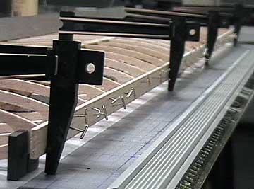
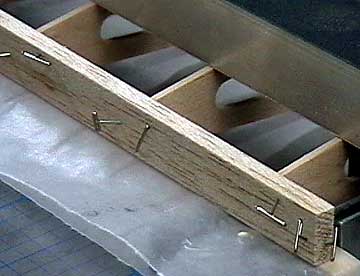
Splitting the Difference

When gluing long parts in place I have found a method that works well.  Obviously if you have added glue then you are working against the clock and you do not want it to become too dry before the part is in place.

The method I use is called splitting the difference.  I pin each end of the part and then pin the center.  Then I put pins midway between the center and the ends.  I continue splitting the difference until all the pins are in place.  This method helps to hold the part in areas that are not pinned yet.

Conversely if you start at one end and work your way towards the other, then the far end is unsupported and can cause problems such as bowing of the structure, etc.


Clamp and pin the sub-leading edge in place. The sub-leading edge is clamped near both tip ribs.  However the part tended to sag in the middle.  When the sagging area was lifted the tip ribs were pushed outward.  I removed the clamps and put a stick under the sub-leading edge to support it and then put the clamps back.

This is an example of what I mean when I say I find a way to put a part on properly before adding glue.  Gluing the sub-leading edge in place is certainly not a difficult task.  A dry run turned up a minor problem (which it often does) that would have made this step more difficult than necessary when the clock is ticking (glue is drying).  I solved the problem which made attaching the part simple and trouble-free.

Avoid putting clamps in areas between ribs as it will cause the structure to distort.

When I was satisfied with the fit I removed the clamps and the sub-leading edge.  Glue was added to each rib and the sub-leading edge was put back in position.  Clamps and pins hold it in place.

It is fully in contact with every rib minimizing the amount of glue used and maximizing the strength of the joint.

Note that the clamps are positioned as closely as possible to a rib rather than between ribs.  The clamps used here are made by Hayes and are very useful.

This step took 10 minutes (including aligning and clamping)

Elapsed time 42 minutes

The trailing edge glued and pinned in place. The trailing edge was glued in place using a method similar to the sub-leading edge.
The trailing edge is pinned to the block supporting the aft portion of the wing to prevent the trailing edge from moving. Notice that I have placed a piece of waxed paper between the ribs and the support stick at the aft end of the ribs.  This is to prevent the stick from becoming glued to the wing.

The trailing edge is pinned to the stick in a few places to prevent it from shifting when pinning it to the ribs.

This step took 8 minutes

Elapsed time 50 minutes


All the sticks used in this construction are left oversize.  The excess length will be trimmed and sanded along with the excess sheeting when that time comes.

At this point I left the wing to dry over night.  Less than an hour has elapsed.  Using CA may have shaved a few minutes off here and there, but I have never known it be the great time-saver it is marketed as.  In fact, the folks marketing CA try to capitalize on people's impatiencea trait that is counter-productive to good model building.  That being said, if you do not mind the price, the mess, the clogged tips and risking your health then CA will get the job done.

Prior to adding the wing sheeting there are a few miscellaneous details that need to be addressed.  The next page will cover the remaining steps necessary to prepare the wing for the sheeting.


Previous —
Next —

Installing Wing Ribs and Shear Webbing
Miscellaneous details

Comments about this article


Back to Wing Construction Example
Airfield Models Home


Copyright © 2003 Paul K. Johnson