Airfield Models - Wing Construction Example

Jigging and Dry-Fitting a Model Airplane Wing

December 18, 2021


Home
About
What's New
History
Models Gallery
Model Building Safety
Articles
Mail & FAQ
Site Map
Site Feedback
Contact
Add to Favorites
Comments
Search Airfield Models

Back to Wing Construction Example


Airfield Models (http://www.airfieldmodels.com/)Jigging and Dry Fitting a Model Aircraft Wing

I will be building this wing upside down.  The only reason that it matters in this case is because the first side that is sheeted will be the bottom of the wing.

The servo hatches and mounts must be completed before sheeting the top of the wing.  Other than that, the wing has a symmetrical airfoil and no wash-out either side can be up.

Before I start gluing in ribs, shear webs and spars, I ensure that I have time to complete the job.  I will explain why when I get there.  In this case I am keeping a clock nearby and timing each step of the construction to make a point.

Why Dry Fit?

Dry fitting is simply assembling parts without glue.  It is an important step in any construction.  It will bring to light any trouble areas and provide you with the opportunity to make corrections before you get into trouble.


Use a straightedge to ensure the spar(s) are absolutely straight. 
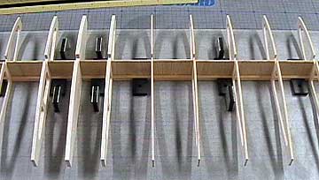
Lay a piece of waxed paper, cling wrap or polypropylene drop cloth material on the board to prevent the wing from becoming glued to the board.
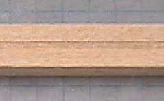
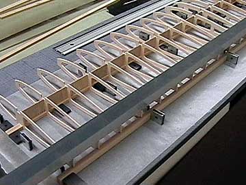
The first spar laid on the board will determine how straight the wing is.  If the spar is wavy, so will be the wing and it can not be corrected.   Be sure you understand that.  Getting this one piece properly aligned will go a long way toward keeping the wing straight.

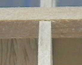
If this part is not straight then you can sand the leading edge and trailing edge straight, but the airfoil will also be wavy and the sheeting is not going to be thick enough to allow you to sand the wing to a uniform shape across the span.
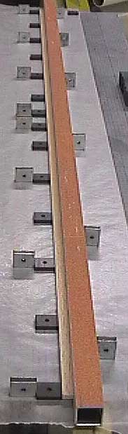
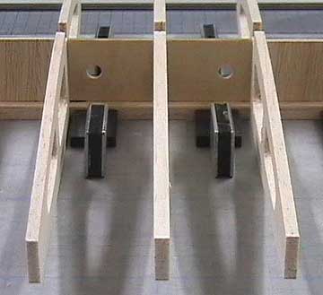
I lay a straightedge on the board and then push the spar up against it.  Pin the spar in place and then remove the straight edge.  If you use magnets then hold the magnets that are already in place so they can not shift and put magnets on the side where the straightedge was.

This is a very important step.  Do not rely on the plans to be straight because they probably are not.  Paper shrinks, expands and warps due to humidity.

This step was 4 minutes.

I put shallow notches in spars to make it easier to align shear webbing. Note that I have cut a shallow groove in the spar to receive the shear webs.  This is an optional step, but it makes adding the webs much simpler.  Additionally, if you finish the wing with transparent covering and the webs are not straight and centered it is noticeable.  The groove gives the webs a much neater appearance as well as giving the webs more glue area.
The ribs and shear webs are placed on the spar to check the fit.

Before gluing anything, I make sure everything fits.  All the ribs, shear webs and both spars are put in place.  This photo was taken before adding the upper spar.

Now you can see why I say the Great Planes building board does not come with enough magnets for real world use.  I bought a second pack of magnets as well as magnets from various other sources.  Details here

Ideally I would like four magnets on every rib to hold it perpendicular (vertically) to the board and perpendicular (fore/aft) to the spar.

The top spar is too high due to the shear webs being too high.  The webs need to be trimmed slightly.

Notice that the upper spar does not fully seat into the rib notch.  The top of the spar should be flush with the ribs when properly seated.  This problem is due to the webs being slightly too tall.

Trim the webs so that the spar fully seats but still makes contact with the webs.

The above step and trimming the webs took 11 minutes.

Elapsed time 15 minutes

The center webs are plywood to receive the dowels that key into the former in front of the wing leading edge. Holes are drilled in the plywood webs for the wing dowels.  These webs are not dihedral braces.  In fact, there are no dihedral braces in this wing because it will be strong enough without them.  All sticks and sheeting run full span and the wing has a moderate aspect ratio.  I have built several wings similar to this and have never had a wing fold in flight.

Drilling the holes should have been done during parts fabrication so I am not counting this time as part of the build time.  If you care it was about 5 minutes.

Note that the ribs on each side of center will sit directly on the wing saddle.  In this case the outside measurement between these ribs is 3-1/2".  That means the fuselage will be 3-1/2" wide at the saddle.  This is an important measurement so I wrote it down.  Remember, I am building without plans.

The trailing edge of a wing often is blocked up during construction.  The ribs should be pinned or weighted to keep them in contact with the block. A stick of balsa is placed at the aft end of the ribs to support them with the spar flush on the building board.  Use the same method as used when laying down the main spar to ensure the stick is straight.

The same straightedge will weight down the aft end of the ribs during construction to prevent warps as shown here.  Alternatively, the ribs could be pinned to the stick.  Be careful not to move the ribs out of position when setting the weight in place or pinning the ribs.

This step took 3 minutes

Elapsed time 18 minutes


Again, no glue was used here.  This is a dry-fitting to ensure construction will proceed smoothly.  This step should always be taken regardless of what you are building.  Murphy has decreed that if you put glue on a part before fitting it then it will not fit.

At this point I am satisfied with the fit of the various parts and ready to proceed with gluing them in place.  Before I can do that I have to pull all the ribs and webs back out leaving only the lower spar and trailing edge support in place on the board.


Previous —
Next —

Preparing to Build a Model Aircraft Wing
Adding the Ribs and Shear Webs

Comments about this article


Back to Wing Construction Example
Airfield Models Home


Copyright © 2003 Paul K. Johnson