Airfield Models - Model Aircraft Engines

Mounting Model Airplane Engines

December 19, 2021


Home
About
What's New
History
Models Gallery
Model Building Safety
Articles
Mail & FAQ
Site Map
Site Feedback
Contact
Add to Favorites
Comments
Search Airfield Models

Back to Model Aircraft Engines


 Airfield Models (http://www.airfieldmodels.com/)Model Aircraft Engine Mounts

The engine mount is a crucial component of the propulsion system.  It is as simple of a system as possible while still being strong and reliable.

Most two and four stroke glow engines have mounting lugs cast as part of the crankcase.  These engines are designed to be mounted on beams.  The type of mount you choose is usually personal preference.  However, there are times that you do not have a choice such as models having built-in wood beams.

Beam mounts are usually found on profile models or older designs (pre 1970).  The vast majority of modern designs have a mount bolted to the firewall.  Engine mounts can either be plastic (fiberglass reinforced nylon) or aluminum.  They come in one or two pieces.  Two-piece mounts can either be completely independent or interlocking.


Typical Engine Mounts

In this section when I use the word "size" I mean crankcase width.  That is the primary factor used to determine if an engine will fit in a mount.  Other factors are the length of the mount and the width of each arm on the mount.  Whenever possible, the engine lugs should not overhang the outer edges of the engine mount arms although a very minimal overhang is usually OK.

A variety of commercial engine mounts In the back row are one-piece mounts by a variety of manufacturers.  The aluminum mount in the upper left is made by O.S. Engines and is pre-drilled and tapped.  All other mounts shown here are fiberglass-reinforced nylon.

In the front row are two-piece mounts.  In the lower right is a two-piece interlocking mount.  I have never seen a plastic mount that was pre-drilled with the exception of some mounts made for Cox 1/2A engines (.049 range).

Independent mounts allow mounting of any engine if the mount is strong enough to withstand the power of the engine.  These require new holes to be drilled in the firewall if a different width engine is used later.  Interlocking mounts hold a specific range of engines with a single set of holes drilled in the firewall.

One-piece mounts are preferred due to their additional strength and rigidity.  They will only accommodate one size engine.  Changing to a different size engine requires a new mount and usually new holes in the firewall.

If you know you might change engines then the easiest thing to do is use a two-piece, interlocking mount or set up the firewall for a second engine mount when you are building the firewall.  Plug the unused holes with silicone sealant.


Drilling the Engine Mount

There is not much tolerance for error when drilling an engine mount.  I strongly recommend that you use a drill press and seek assistance if you have never done this before.  If the holes are off enough to make it difficult to thread in the bolts then the mount or crankcase may crack or the bolts may break under additional stress.  Obviously these are bad things that you don't want to happen.

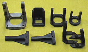
I use a blind nut (AKA T-nut) that fits in the mounting hole on the engine lug.  You can get blind nuts in sizes from 2-56 up.  Remove the barbs from the blind nut or bend them down so they are flush with the flange.  Remove the head from a screw and then chuck it into your drill.  Use a file to put a point on the end of it.  Four sets of these allow you to mark all the mounting holes.
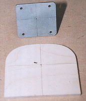
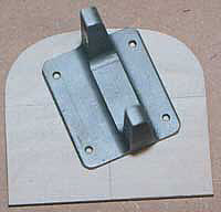
It helps if you find a way to clamp the engine to the mount while marking the holes.  
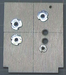
Place a punch over the headless bolt and tap it with a small hammer to mark the mount.  If you can clamp the engine to the mount then tightening the clamp will usually mark the hole locations well enough that you will not have to use the hammer.  Save these sets as you make them for use next time.

Marking Bolt Locations on an Engine Mount

A simple way to mark engine mounting bolt locations on an engine mount using blind nuts

You can use the engine measurements included with the engine to drill the mount, but you have to be able to measure accurately.  If you are using a nylon mount, the engine may spread the arms of the mount when you put it in.  Obviously the holes will not be spaced as they were when you drilled them.

My suggestion is do not use a mount that is a squeeze fit on the engine.  You can usually file away a little of the upper inside corner of each arm so the engine does not rub against the arms.  The only part of the engine that should touch the engine mount is the bottom of the mounting lugs.

If you are using a plastic mount do not lubricate the bit.  Use a slow speed on your drill or drill press so that you do not melt the plastic.  If you are drilling a metal mount, then use some type of oil to prevent galling, over-heating or premature dulling of the bit.  I just use whatever oil is handy usually sewing machine oil.

If you decide to tap the mount (which I recommend), then be sure to back the tap out frequently to clear chips from the cutting threads.  If you fail to do this you may break the tap.  At that point you may as well buy a new tap and engine mount unless the tap broke far enough from the mount that you can grip it with pliers and back it out.  You might save the mount, but you will still need a new tap.

Some engine mounts and all beam mounts have beams that are parallel (top and bottom of beam) so that a bolt and locknut can be used to hold the engine in place.  Many engine mounts have beams that are not parallel and are designed to be tapped for the engine bolts or use sheet metal screws.

Personally, I prefer to tap all mounts because I have seen too many people have problems with nuts vibrating loose, mounts crushing, etc.  If you install your hardware correctly, you shouldn't have any of these problems, but if you tap the mount, then these problems are not an issue.

Tip: If you tap a plastic mount, measure the amount of bolt that will thread into the mount.  After drilling the holes, tap all but the last 1/4" that the bolt will thread into.  This will turn the mount into a self-contained lock-nut.

Nylon-insert lock nuts are designed for one time use.  If you remove the nut you should replace it because the nylon will not work properly afterward.  Also, if the engine gets hot enough, it can also heat the bolts to the point where the nylon insert softens.  Obviously this will destroy it is "locking" properties.

A lock nut can realistically be removed a couple of times and still be ok, but if it gets to the point where it threads on with little force then it is not a lock nut any more.


Mounting the Engine

The most important thing to remember when mounting your engine is that the arms that the engine bolt to must be in the same plane.  If the arms are distorted there is a good possibility the engine will be damaged.  There may also be excessive vibration that can damage radio equipment, the airframe or cause fuel foaming.

Most commercial mounts can be used as is although some have arms that are slightly distorted due to cooling effects on the plastic after the mount is pulled from the mold.  A few minutes with a sanding block will put the arms in the same plane.

I recommend using stainless steel, socket head bolts for mounting the engine to the mount and the mount to the firewall.  Many kits and ARF's come with soft steel, slot-head or Phillips bolts that should simply be discarded.  A flying buddy recently had two bolts shear on his profile fun-fly ship.  Stainless steel hardware is much stronger and only marginally more expensive.

Another problem that occurs is difficulty engaging a driver straight into the bolt because there is something in the way.  This usually results in a distorted head which makes the bolt very difficult to remove.  Ball drivers are excellent in this situation which is why I recommend the socket head bolts.

Assemble the engine and hardware in this order:

  • Place the engine in the mount.  Ensure that it sits flat on the beams without having to force the beams apart.

  • Slide a lock-washer on the bolt unless you're using lock nuts.

  • Slide a flat washer on the bolt.  This washer will prevent the bolt or lock washer from galling the lugs on the engine.

  • Put the assembly through one of the holes in the engine lug.

  • If you tapped the mount, then thread the bolt all the way in until it just becomes snug then back off the bolt one turn.

  • If you chose not to tap the mount, then slide a flat washer on the bolt where it exits the bottom of the beam and then thread on a lock nut until the it just becomes snug.  Back it off one turn.

  • Repeat these steps until all four bolts are in place.

  • Tighten each bolt securely.


Attaching the Engine Mount to the Firewall

The back of the engine mount and the front of the firewall must be flat.  Plywood supplied in kits is never flat and I have actually sanded through a lamination of the plywood while flattening the firewall.  Use a good sanding block and a circular sanding motion to "hone" the firewall perfectly flat.

Be sure to sand the back of the mount as well.  Be careful not to sand in an unintentional thrust adjustment.  Plastic mounts always have areas of the mount that are lower.  I don't worry about getting the entire back of the mount flattened to the lowest part.  I just get most of the perimeter flat.

The blind nuts for the engine mount are easy to install before the firewall is glued in place.

It is always easier to build the firewall before it is glued into the fuselage.  Set up everything that will be on the firewall including the engine mount, throttle linkage, and if used, the nose gear and steering linkage.  Also drill the holes for the fuel lines to pass through and be sure to sand them smooth so they do not cut the tubing.

Blind nuts are installed on the back of the firewall to install the engine mount.  It is difficult if not impossible to get to these nuts after the aircraft is completed, so using hex nuts is not an option.  I have complete confidence in blind nuts and never had one strip out.

If the holes the blind nuts go into are too large, the nuts can start to pull into the firewall when the bolts are tightened.  I usually drill the holes for the blind nuts slightly undersize and then tap them in place with a small hammer.

A simple way to rotate and engine mount on the thrust line

I was trying to find the position where the muffler would exit the bottom of the fuselage along the centerline of my Sig Smith Miniplane.  While this is not a difficult task, I had to keep rotating the engine while trying to keep it centered on the firewall and on the thrust line.

To be really precise, I would have to measure the engine mount and draw a diagram.  I wasn't up for all of that.

My solution was to drill a shallow (1/8" deep) 1/16" hole in the back of the engine mount and then drill another shallow 1/16" hole in the center of firewall.  A short 1/16" music wire pin is inserted in the hole in the firewall.

A simple way to rotate and engine mount on the thrust line

Now all I have to do was set the engine mount on the pin and rotate the mount without worrying about it remaining centered.  When I like where it is, I simply mark the locations for the mounting bolts and drill the holes.


Engine Thrust Line Adjustments

If your aircraft needs a thrust adjustment then use washers between the mount and the firewall for test flights.  Permanently replace the washers with a wedge sanded from plywood when you are satisfied with the thrust adjustment.  Fuel proof the wedge and bolt it between the engine mount and the firewall.

If you continue to use washers they will sink into the plywood firewall over time, change the thrust setting and allow the bolts to loosen.  A wedge is also superior to washers because it fully supports the engine mount.

The back of the propeller should be on the centerline of the aircraft viewed from above and on the thrust line in side view.  Many designs have right and down thrust.  If the engine has right thrust then the engine should be moved toward the left side of the firewall (looking from the cockpit) to put the back of the propeller on the centerline of the aircraft.

If the engine has down thrust then the engine should be moved up on the firewall.  When the engine is located properly mount the cowl so that it matches the engine.

Important! Never change the thrust line of the engine to match the cowl.  The cowl should be matched to the engine.

Also see


Previous —
Next —

Types of Model Aircraft Engines
Setting up the Throttle Linkage

Comments about this article


Back to Model Aircraft Engines
Airfield Models Home


Copyright © 2003 Paul K. Johnson