Use sewing machine oil or another
light oil to thoroughly coat every part while the engine is disassembled. The
parts don't need to be
dripping oil, but they do need to be coated. Sewing machine oil is
safe for all parts of all engines that I am aware of.
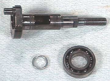 |
The crankshaft and bearings must be in place before
anything else. Shown here are the rear ball bearing (not all engines
have ball bearings) and an aluminum spacer having a purpose I have no idea
about. But I know where it goes, so I don't need to know what it
does. The rear bearing is not sealed. It can go in facing
either direction. |
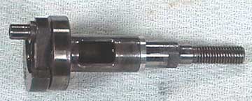 |
The rear bearing and spacer in place on the crankshaft. |
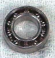 |
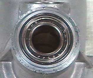
The front ball bearing is sealed on one side. The
sealed side faces out to keep dirt from entering the bearing and the
engine. Shown here is the unsealed side of the bearing. |
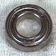 |
The sealed side of the front bearing. Again, not
all engines have ball bearings. Economy engines often have bronze
bushings that should not be removed. |
 |
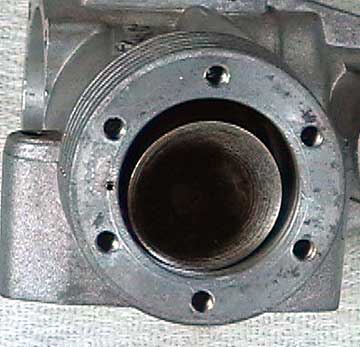
The crankshaft is inserted into the engine through the
backplate opening. The bearing is a tight fit and unable to seat.
To remove the bearing, the engine was heated in the oven.
Aluminum
expands more than steel so heating the engine allows the bearings to
fall out.
The reverse is also true. Heating the engine
allows the bearings to go back in place which was what was required
here. I put the crankcase in a 250°
oven for about 10 minutes. Only the crankcase was placed in the
oven — not the crankshaft and bearing. |
 |
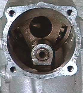
After heating the case the front bearing falls into place
easily. The sealed side is out. |
 |
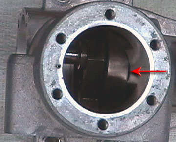
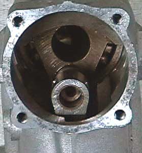
Heating the case allows the rear bearing to slide into
place more evenly. However, you can see that it is not fully
seated.
When the crankshaft is seated properly the opening in the crankshaft will align with
the carburetor hole or at least be much closer.
To remedy the
situation, I put the thrust washer on and then bolted a propeller to the
engine. Tightening the propeller nut pulled the crankshaft and
rear bearing into place. |
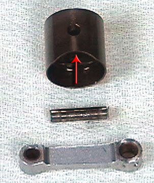 |
The piston, wrist-pin and connecting-rod. Note the
cutout on the skirt of the piston. This cut-out goes forward and
prevents the piston from contacting the rear bearing. In some
cases there is a relief at the back of the piston to prevent it from
contacting the backplate or the rear bearing. This is why you need to examine your
engine before disassembling it. Putting parts in backwards is easy
to do.
Note that the connecting rod has two different size holes. This
ensures that the right end is in the piston, but it can still be turned
around backwards. This engine, for example, requires the connecting
rod to face a certain direction. If it is backwards, the engine
will not turn over. Each engine is unique, so this may not be the
case with yours. |
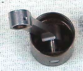 |
The assembled piston. Note the oil hole in the bottom of the
connecting rod. |
 |
The piston goes into the engine before the liner. If you put the
liner in first, you will not be able to put the connecting rod over the
pin on the crankshaft. |
 |
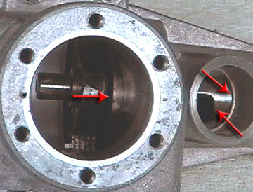
The engine is shown here upside down. Most frequently, the pin on
the crankshaft has to be at its top position in order to put the
connecting rod on the crank-pin. |
 |
The connecting rod seated properly on the crankshaft pin. |

