Airfield Models - How To

Make Carbon Fiber Pushrods

December 19, 2021


Home
About
What's New
History
Models Gallery
Model Building Safety
Articles
Mail & FAQ
Site Map
Site Feedback
Contact
Add to Favorites
Comments
Search Airfield Models

Back to How-To Articles


Airfield Models (http://www.airfieldmodels.com/)How to Make Carbon Fiber Pushrods

This article outlines only one type of tube pushrod.  I can't tell you if this pushrod will be strong or rigid enough for your application but I can tell you that this pushrod is very strong.  If the length of the finished pushrod allows it to flex then you can add supports to the structure as needed.

Supports don't need to be anything more than hard balsa or light plywood strips glued to the fuselage sides and reinforced if necessary.  The supports should have a hole large enough for the pushrod to slide through without binding.  Usually one or two drill sizes larger than the pushrod works well.

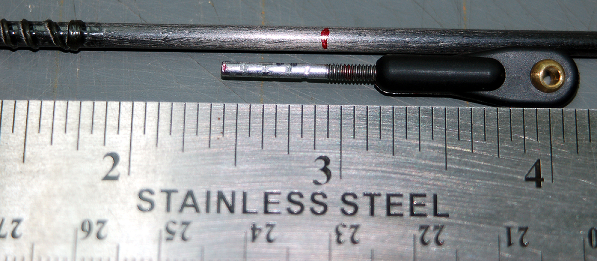
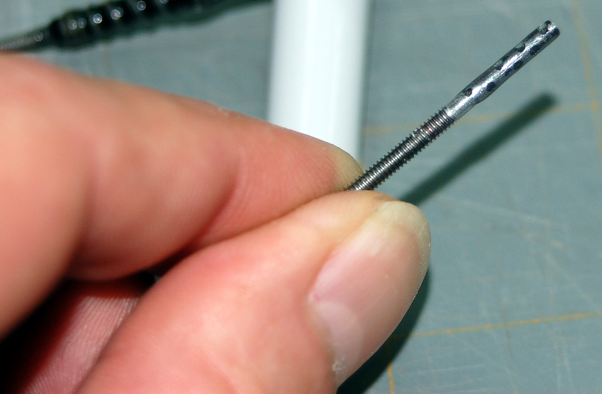
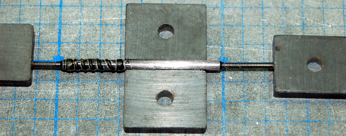
This style pushrod depends on the threaded rod being a good fit inside the tube.  Very good pushrods can be made with fiberglass or carbon fiber tubes that are significantly larger than the threaded rod but the technique for making those pushrods is much different than what is demonstrated here.

While you can make these larger pushrods using items you probably have in your shop you can also construct a pushrod using commercially available ends that accept the threaded rod and glue into the end of the tube.  Again, those are pushrods having diameters significantly larger than the threaded rod such as 1/4" fiberglass pushrods with 2-56 of 4-40 threaded rod.  And again, they require a different method of construction.

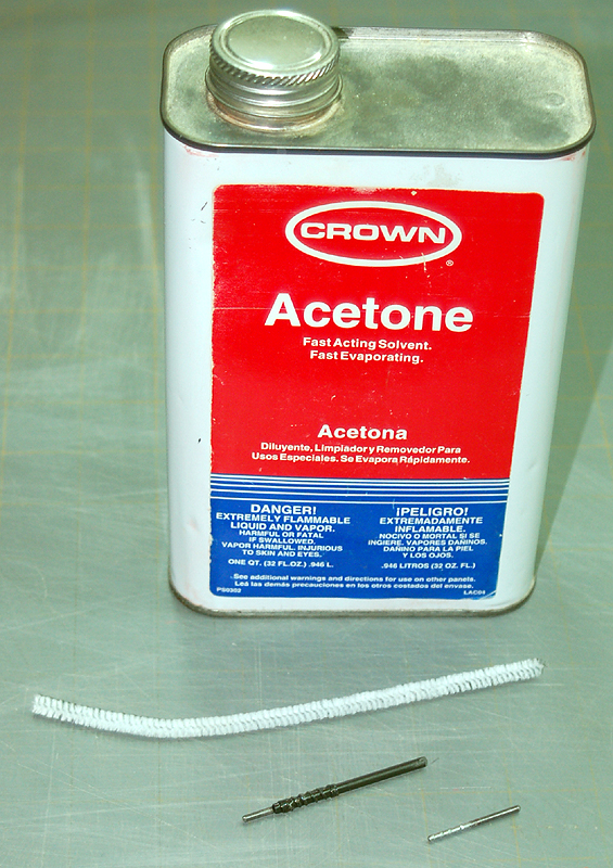
The pushrod style shown here works for any type of tube that is light, rigid and that epoxy will adhere to.  Therefore aluminum or fiberglass tube will also work.  However aluminum is much weaker and is normally a really poor choice for anything other than park flyers where the lighter weight of thin-wall aluminum is preferable to carbon fiber tubes that are heavier due to having thicker walls.

Before you Start

The servo must be securely mounted in its final location.  Remove the servo arm.  Choose the arm you want to use but leave it off the servo for now.

The control surface must be attached and centered.  For example, if you are making a elevator pushrod then the fixed stabilizer should be secured where it will be glued if it's not glued already.  Mount it accurately even if the mount is temporary.  That means lots of pins, appropriate clamps or whatever will keep the stabilizer in place.

It is a very good idea to find a way to lock the movable control surface in the neutral position.  Having a control surface flopping around invites incorrect and inconsistent measurements.

Turn on your transmitter.  If you are using a computer radio then it's best to choose a memory position for your new model and reset (erase) it.  That will ensure that all the trims, sub-trims, etc. are at neutral.  If you don't want to wipe the memory for that memory slot then you will need to center the trim and the sub-trim for the channel in the menus.

If you aren't using a computer radio then move the trim for the channel in question to neutral.

Plug the servo into the correct channel of the receiver.

You can use a switch jack or just plug the battery directly into the receiver to turn it on and unplug it to turn it off.

Your servo should now be centered.

If your control does not require differential movement then use a straightedge aligned with the control horn and the approximate hole position of the servo arm.  The pushrod itself should be straight and will work well if it's long enough to see that it's aligned.  This doesn't have to be perfect but get it as close as you can by eye.

Now put the servo arm on the servo as close as possible to 90 to the line from the servo to the control horn.

Do not adjust anything on your transmitter to rotate the servo arm for better alignment.  For the remainder of this article you should not be making any adjustments to electronic trims of any type.  All of that comes after the model is completed and you're adjusting everything for the first test flight.  For now we're trying to get as mechanically centered as possible.

If the control surface does require differential movement and you know how much the arm needs to be rotated then you will be rotating from 90, not from parallel to the fuselage side or some other construction centerline or whatever.  Everything is adjusted from the line from servo arm to control horn.

If you don't know how much the arm needs to be rotated for differential movement then you just have to do the math or give it your best guess.  Any plane that needs differential isn't going to be critical because planes that fly with precision don't have controls that need differential except very, very tiny bits.  If you're a good enough pilot flying a good enough contest ship that needs a 1% adjustment here or there then you don't need this article.


Making a Carbon Fiber Pushrod

I buy my threaded rod from Micro Fasteners.  The rod at the top of the photo shows what you get in terms of thread length.  These rods are 12" long and threaded at both end.  I typically use only a short length of the rod and get two pushrods from each piece.

Many hobby retailers sell threaded rod that is threaded only on one end and it costs more per piece.

I cut off excess thread because the threaded portion of the rod is weaker meaning it will bend more easily.  I cut off excess thread leaving enough to provide reasonable adjustment to achieve flight trim.

Small notches are made using a file or an emery cut-off wheel in a moto tool.  The notches provide something for epoxy to bite into.  While these notches are good they don't need to be this deep.

Determine the overall pushrod length

Before you do this you need to have done all that radio stuff I mentioned earlier.  If you skip those steps then don't be surprised when your pushrod is 1/4" too short and there's nothing you can do but start all over with a new pushrod.

Measure the distance from the hole in the servo arm to the hole in the control surface horn.

This article details a short pushrod for an aileron that requires no differential.  The pushrod needs to be 4" from hole center to hole center.

Your goal is to have the maximum amount of adjustment from the linkage while always having it threaded far enough onto the rod that there is no danger of it coming off in flight.

Begin by threading the linkage onto the rod only as far as you feel the linkage can be threaded out and be secure.  For example, I normally consider a linkage to be secure only if it is threaded on at least eight complete turns.  The number of minimum turns depends on the linkage and rod used.  Just keep in mind that if the linkage comes off your plane is done.  So don't try to be clever here.

Mark the rod at the base of the linkage using a Sharpie marker.

Now thread the linkage onto the rod as far as it will go.  Mark the rod again.  You have now marked the extremes of adjustment.

Remove the linkage from the rod and make a mark centered between the two marks you just made. That is the neutral position.

This is usually an eye-opener for people who think they have a lot more adjustment than they actually do and it should make it very clear why your pushrods need to be made accurately.  There is nothing difficult about it.  It's just a matter of caring enough to take the time to do it right.

What you quite possibly might find is that you have only 1/8" to 1/4" adjustment in either direction for a total of 1/4" to 1/2" overall adjustment.

One thing I worried about early on was what if I needed all of the adjustment in one direction.  For example, I have 1/4" in both directions but I need the whole 1/2" or close to it in one direction.

If that happens there is something else wrong with your plane - probably balance.  If your plane is built properly and balanced then all control surfaces should trim your model with the surfaces very close to neutral.

By the way, you get a lot less useable adjustment from this type ball link than a similar size clevis.  A clevis may give you a full 1/2" of adjustment where a ball-link may only give you 5/16".  What that means is that you need to be much more careful with your measurements and construction.

Thread the linkage onto the rod to the neutral position you found in the last step.
One end of the pushrod should be completed at this point.  Normally pushrods only need one adjustable end.  This pushrod needs a ball linkage at both ends.

Center the finished end at 0" on your ruler and the loose end at the pushrod length you measured in the first step.

Note that the completed end is wrapped.  Wrapping the pushrod end will be covered later in this article.

Mark the pushrod tube where the thread ends on the rod that is to be glued.  Very carefully cut the pushrod at this mark.  Carbon fiber splits and splinters very easily.  A razor saw can cut the tube but it will ruin your saw.  I use a cut off wheel very slowly to avoid damaging the pushrod.
Use acetone to clean the pushrod and tube to ensure a good bond with epoxy.  I put a little on a paper towel to thoroughly clean the metal rod.

Use a pipe cleaner with acetone to clean inside the tube.  While acetone evaporates quickly it takes longer in enclosed areas so don't drench the inside of the tube but do clean it thoroughly with the pipe cleaner.  Allow the tube to dry for several minutes before gluing the threaded rod in place.

Use slow-cure epoxy - at least 30 minute.  Faster epoxy can be very brittle when cured so I would never trust 5-minute epoxy for anything critical.

Mix the epoxy thoroughly.  I use a small wire or toothpick to spread epoxy inside the tube end.

I also coat the threaded rod with the same batch of epoxy.

Slide the rod into the tube.  Wipe up glue that smears off as it happens to avoid having a big dripping mess of epoxy all over the pushrod, you, your bench or your floor.

If the rod fits properly inside the tube then a seal is created when the rod is slid into the tube.  That pressure will push the rod back out.  Find a way to hold the rod in place while the epoxy cures.  You should have already figured out the system you will use to accomplish this before you mix the epoxy.

You'll notice I've wrapped the ends of the pushrod.  I don't know if it's necessary or not.  I see a lot of carbon tube pushrods at the field that have a rod glued in and aren't wrapped.  I like the extra security because it's not too difficult to split carbon fiber tube along its length.  The wrapping will prevent that from happening.  Linkage integrity is extremely important if you want your planes to survive flight so I don't take any chances with them.

We are fortunate to have some very strong string available to us in the form of fishing line.  You don't need monster shark line for this.  Any good 10# line will work.  Make a fold in the line about 1-1/2" long.  Beginning at the end of the tube tightly wrap the line around the tube at an approximate 30 pitch.  Keep wrapping for about 1/4" past the point where the rod ends inside the tube.

Continue wrapping in the same manner back to the end of the tube.  Put the end through the loop you made when you folded the thread and pull the other end which is under all the wrapping to pull the loose end under the wrapping as well.  It takes some practice to do this.

Finally mix up some good slow-cure epoxy.  Set it in a shallow container filled about 1/2 way with warm water.  Stir the epoxy and when it has warmed it will be lower viscosity.  Use a disposable epoxy brush to fully saturate the wrapping.  Just work at it a while until you're sure it's completely coated.  Finally wipe up the excess and allow the epoxy to cure.

You now have an incredibly strong pushrod.  Again, you have to ensure it doesn't flex under load which may mean adding some supports at intervals inside the structure.


Previous —
Next —

How-To Articles for Model Builders
How to Make a Set of Ribs for a Tapered Wing

Comments about this article


Back to How-To's
Airfield Models Home


Copyright © 2011 Paul K. Johnson