Building
the
Thunder Tiger Raptor 30 V2 Helicopter — Steps Sixteen
and Seventeen
If you're at this point and you haven't charged the batteries
for your radio yet, then get them on charge because you'll need the radio
soon.
Step Sixteen
— Servo Installation - Part 1
This step is on page 14 of the Instruction Manual.
Note that the balls are mounted to servo arms and the
throttle arm using machine screws and hex nuts.
Be sure to
Loctite this hardware so it doesn't vibrate loose.
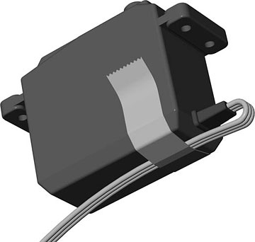
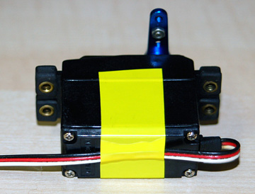
Use a good quality tape to secure the lead to the bottom of
the aileron servo. Be sure the lead isn't strained where it
exits the case.
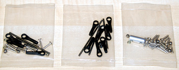
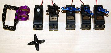
Parts bags for this assembly.
Servos and a tail boom mount for the tail rotor servo.
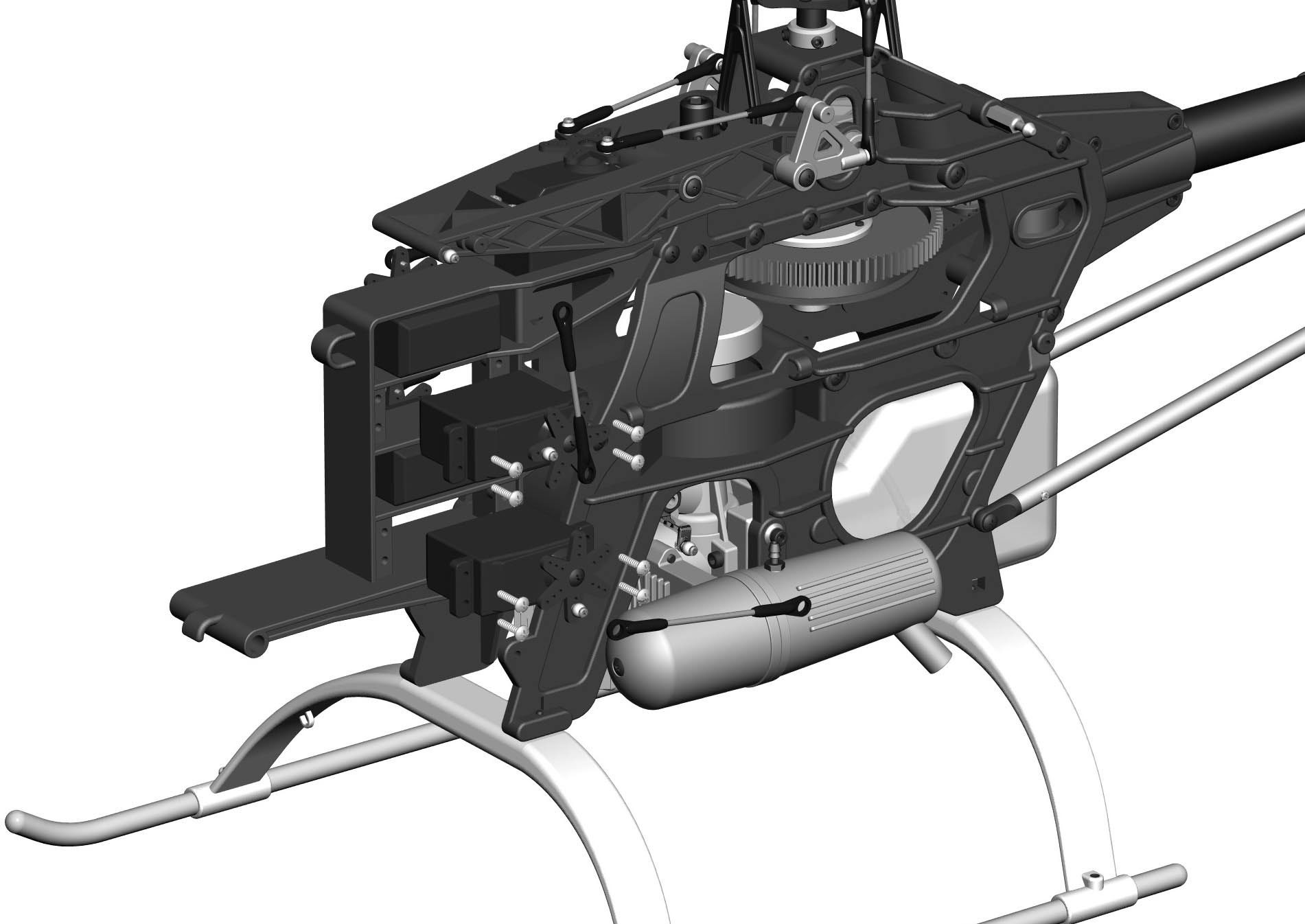
This is the only upgrade I suggest for your heli. When I built my
first Raptor there was too much drag in the stock setup. The setup
is essentially the same in the new Raptor so I didn't even attempt to use
it.
If you want to use the stock setup then you're on your own
because it will not be covered in this article. I'm sure a lot of
pilots have gotten it to work fine.
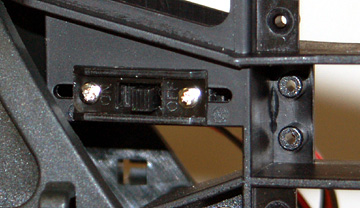
Mounting the receiver switch is actually part of the
next step, but it's
easiest to install before the servos so go ahead and install it in the
molded mount on the right side of the servo frame.
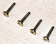
Servo mounting screws.
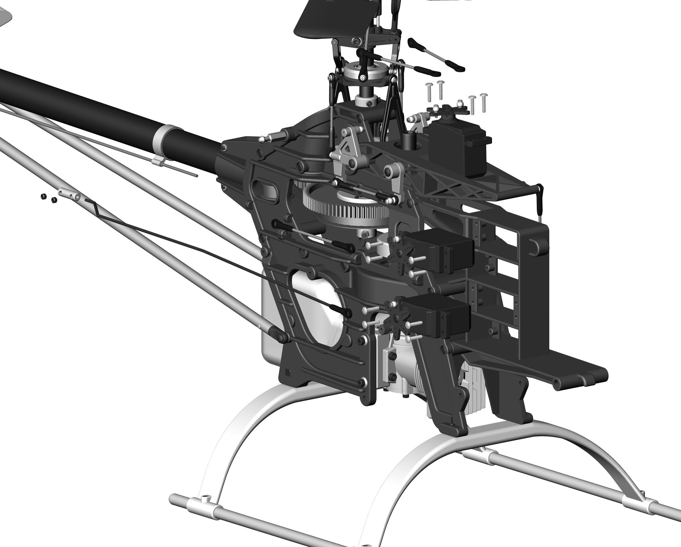
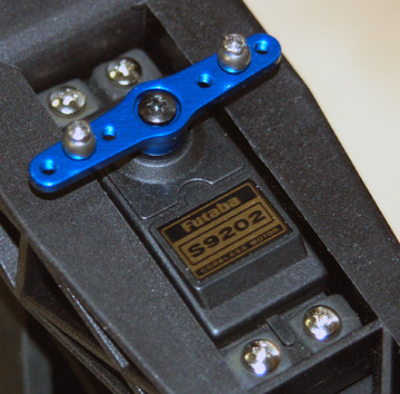
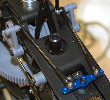
Mount the aileron servo to the top of the collective
pitch control arm.
All servos mount with the
output shaft toward the rear of the helicopter.
Make two 73 mm aileron linkages and connect them to
the aileron servo and the aileron control levers.
This is
when I realized I had mounted the aileron control levers with the balls on
the outside instead of the inside. Instead of changing the location
of the balls I simply swapped the levers.
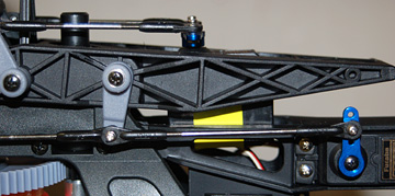
Mount the elevator servo in the top opening of the
servo frame.
Make the 86 mm elevator linkage and
connect it to the elevator servo and the elevator control lever.
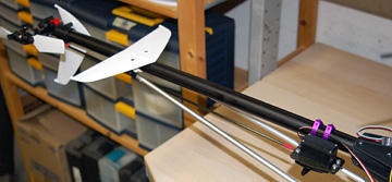
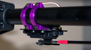
If you use a tail boom mount for the tail rotor servo mount
it well forward on the boom.
You'll have to make a pushrod the correct length. I
used carbon fiber tube with threaded rod epoxied into both ends.
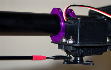
Another view of the tail rotor servo, mount and pushrod.
Step Seventeen
— Servo Installation - Part 2
This step is on page 15 of the Instruction Manual.
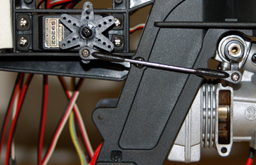
The throttle servo is installed on the left side of
the frame in the lowest hole.
Connect a ball to the servo arm and
the throttle arm.
Make a 75 mm pushrod and connect the servo to the throttle.
Ray Hostetler's book covers throttle linkage geometry in detail and is
suggested reading.
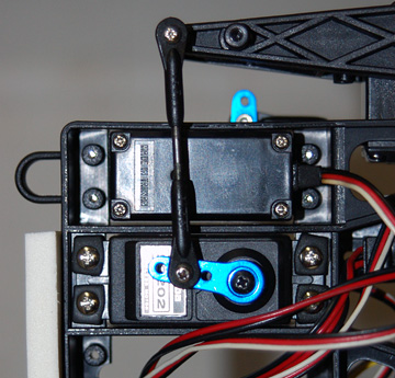
The pitch servo goes in the second hole from the top
on the left side of the frame.
Screw a ball to the servo arm.
Make a 51 mm pushrod and connect the pitch servo to the collective
pitch control arm.
At this point all the servos should be installed and all linkages
should be connected. Note that the length of the linkages given in
the manual are starting points. The output shaft of your servos may
not be in the same location as the servos used when the helicopter was
designed. It is almost 100% that you will need to adjust many of the
linkages to get the correct control geometry of your helicopter.