Using Shear Webs
in Model Airplane Wings and Other Flight Surfaces
Imagine a stick of wood laying on your
workbench. If you hold each end and bend the stick some interesting things happen. On the outside of
the bend the wood is under tension. That simply means it is being
pulled apart. On the inside of the bend it is under
compression - it is being pushed together.
A pair of
spars behave in the same way.
If the wing is bent up, then the lower spar is under tension and the upper spar
is under compression.
It is normally the compressed spar that fails when a wing folds
 Just because a wing fails does not necessarily mean the design is faulty. It could mean that the wing was stressed beyond its
intended limit or that the wing was poorly constructed. Just because a wing fails does not necessarily mean the design is faulty. It could mean that the wing was stressed beyond its
intended limit or that the wing was poorly constructed.
For example a
high
aspect ratio
sailplane wing could probably not survive a sharp pullout from a terminal
velocity dive. However, that does not mean the wing was not designed
properly.
Sailplanes
are not intended to perform this type of maneuver any more than your car
should be able to survive a high-speed impact with a brick wall.
On the other hand, sailplane wings have to be strong enough to withstand
High-G winch launches which requires careful engineering and construction.
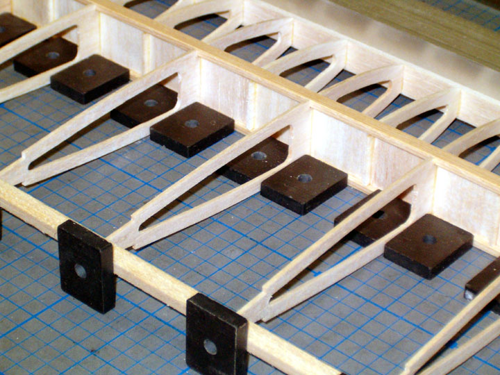
Shear webs essentially turn a pair of spars into
an I-beam. There is a reason why this shape is used
for construction
of buildings. It is light and strong. The webs add tremendous
strength to the wing construction and help prevent
a spar from compressing to the point of failure.
 Some people mistakenly believe that a web glued
to the front or back of the spars is stronger than one between the spars due to additional gluing area. That
simply is not true. It is true that the glue joint probably will not fail,
but the wood can shear off under enough stress and the wing will mostly
likely fail soon after. Some people mistakenly believe that a web glued
to the front or back of the spars is stronger than one between the spars due to additional gluing area. That
simply is not true. It is true that the glue joint probably will not fail,
but the wood can shear off under enough stress and the wing will mostly
likely fail soon after.
However, most of our models are over-built and
shear webs placed on the front, back or middle of the spar will usually be
strong enough.
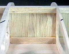
I always put webs between pairs of spars simply because I
know the webs are stronger as well as lighter (less wood and less glue).
Plus they look nicer under transparent coverings.
The grain of the web is vertical because that is
the direction the loads come from. I have seen designs that had webs
arranged with the grain running span-wise. That is absolutely wrong
and if you ever see this in a kit or on a plan, then make the webs with the
grain running vertically between spars.
Try this test: Cut a small square piece of
1/16" balsa wood. Put the piece between your thumb and middle finger with the
grain going from your thumb to your finger. Try to crush the balsa.
Turn the
piece 90°
and try to crush it. You can see that it is very difficult to crush
the wood against the grain. Shear webs use that property to great
advantage.
 Note that webs do the greatest amount of good near the root of the wing.
If you use them in the first 1/3 of the span measured from the root towards
the tip, that will be good enough for most designs. Note that webs do the greatest amount of good near the root of the wing.
If you use them in the first 1/3 of the span measured from the root towards
the tip, that will be good enough for most designs.
I
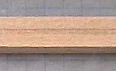
tend to install shear webs along the entire wing span simply because webs weigh practically
nothing. Another thing I do is groove the spar to make installation
simpler. The groove isn't necessary but it helps keep the webs aligned as
well as hold them in place. I use my
Microlux table saw to cut the
groove to approximately 1/64" deep.
As far as I am concerned the webs are worth the
small amount of weight they add and the additional work necessary to
fabricate them. Therefore I use them in almost all of my models even
if the design does not call for them.
John Eaton kindly sent a link that explains the concept of spars and webs in more detail and is more accurate
information than posted here. Thanks John!
|