Dead On Arrival
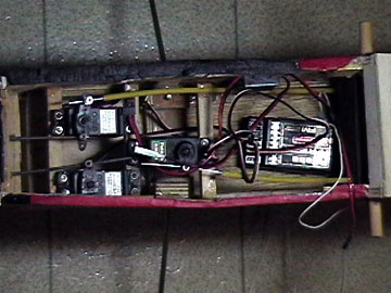
The following image shows the radio installation
in this model. Again, this is how my fellow club member received the
model. This was not his handiwork.
The first thing I notice is the use of
EZ
connectors on the primary control surfaces. This is an extremely poor
practice because EZ connectors often fail in two different ways.
The
set screw can come loose or the connector itself can part company with
the
servo arm.
EZ connectors are inherently sloppy and cause twisting
loads on
servo arms because of the amount they are offset. EZ
Connectors are fine for no or low-load items such as
throttle, but I do not
even use them there. In fact, I do not use them at all. In any
case never use these kinds of
connectors on any flight surface.
Use a
Z-bend, quick connector (uses an L-bend),
clevises
(solder or threaded) or captured
ball links (helicopter style)
instead.
Information about
Pushrods and
Linkages
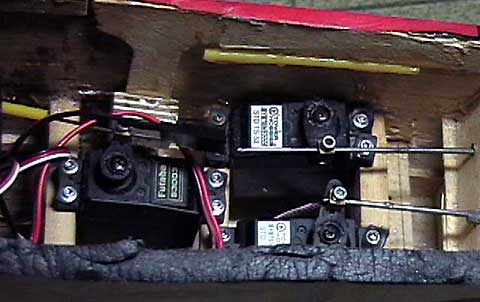
The second thing that is apparent is that the
servo mounts are not in the same plane. The middle rail is lower than
the other two rails by about 3/8" which means the servos are not mounted properly and the
servo arms do not rotate in a plane parallel to the
pushrods.
If you
look closely you can see that the mounting tab of the left-most servo is
actually being bent down under the force of the mounting screws. It is
more difficult to see the other tabs, but they are all like that.
Lastly, notice the servo mounting screws.
Some of the rubber grommets have been over-compressed and have completely
lost their vibration absorption capability. I did not pull the servos
out but I suspect that the eyelets were not installed in some of the
grommets.
It truly disturbs me that
anyone would think this is an acceptable installation. Unfortunately
I see things like this far too often. If you do your
radio installation before you
build the fuselage you can avoid misalignment problems and have a simpler,
more reliable and cleaner installation.
|

